Reading and drawing a circuit
By UK GCSE Physics · independent study · myAudience
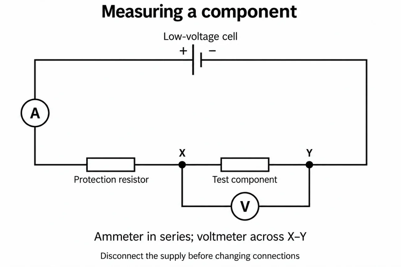
Image: illustration, not a documentary photograph. Original myAudience teaching concept; generated raster independently inspected. · Original generated teaching illustration; source facts attributed in the lesson.
Reading and drawing a circuit
A circuit diagram is a map of electrical connections. It does not show how large an object is or where it sits on a bench. Start at one supply terminal and trace a route back to the other. A switch drawn with a gap interrupts that route; a closed switch joins its contacts. A wire crossing is not automatically a junction: use a clear junction dot where connections meet.
In the symbol set, a cell has one long and one short parallel line; the long line is its positive terminal. A battery has repeated cell pairs. A lamp is a circle with a cross, a fixed resistor a rectangle, and a variable resistor a rectangle crossed by a diagonal arrow. An ammeter is a circle containing A and a voltmeter a circle containing V. Connecting wires are drawn as lines. Recognising the symbol tells you the component, not its numerical rating.
A diode symbol has a triangle pointing towards a bar; its preferred conventional-current direction is towards that bar. An LED adds two arrows pointing away, representing emitted light. An LDR has a resistor inside a circle with two arrows pointing towards it, representing incident light. A thermistor uses a resistor rectangle crossed by an oblique line with a short end stroke. A fuse is a small rectangle with a line through it. These details distinguish devices that can look similar in a rough sketch.
To measure a component, put an ammeter in the current path, in series with it. Connect a voltmeter between the two ends of the component, in parallel with it. Ideal ammeters have negligible resistance; placing one directly across a supply risks a short circuit. Ideal voltmeters have very high resistance and draw negligible current. Use only teacher-approved low-voltage apparatus for circuit work, and ask for a circuit check before switching on.
Trace plate 06 from the long positive cell plate through A, the protection resistor and test resistor to the short negative plate. V connects only between X and Y. Its resistor rectangles, unequal cell plates and circular A/V symbols agree with the current reference. The picture covers this measurement arrangement, not the entire symbol catalogue; practise drawing switches, battery, diode, LED, thermistor, LDR, lamp and fuse separately. The protection resistor is fixed; it cannot vary the supply.
Vocabulary: symbol = agreed diagram mark; junction = connected meeting of wires; series = one route through components; parallel = separate routes between the same two points.
Worked example: A low-voltage drawing has a cell, a closed switch, an ammeter and a lamp in one loop. A voltmeter is across the lamp. Count the instruments in series with the lamp and across it.
Trace the lamp route: the ammeter lies on that route.
Trace the two voltmeter leads: each reaches a different lamp terminal.
There is one series instrument and one instrument across the lamp.
Answer: One ammeter is in series; one voltmeter is in parallel.
Check your understanding: A learner puts A between X and Y and puts V in the only series route. Explain both errors and give the corrected connections without powering the apparatus.
Answer: A must be in the route through the test component; V must form a separate branch between X and Y.
Why: An ammeter has very low resistance and would bypass the test component; a voltmeter has very high resistance and would greatly reduce the series current. Correct topology before energising an approved low-voltage circuit.