Solving a series circuit
By UK GCSE Physics · independent study · myAudience
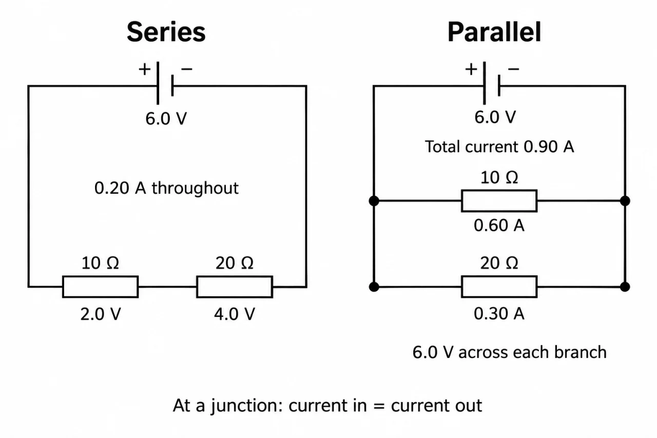
Image: illustration, not a documentary photograph. Original myAudience teaching concept; generated raster independently inspected. · Original generated teaching illustration; source facts attributed in the lesson.
Solving a series circuit
Components are in series when there is one route through them in turn. The same current passes through each component. If a connection opens anywhere in that route, the whole simple loop stops carrying current. A series circuit therefore cannot keep one lamp operating after another part of its only route is removed.
The supply potential difference is shared between series components. Across two resistors the drops add to the supply value in the ideal model. The drops are not necessarily equal: with the same current in each, V = IR means the larger resistance has the larger potential difference across it. Equal resistances give equal drops under the same conditions.
For series resistors, total resistance is R_total = R1 + R2. Every coulomb has to pass through both resistive components, so adding one requires more potential difference to sustain the same current. With a fixed supply, adding resistance reduces current. This is different from saying the second resistor receives leftover current: there is only one steady current throughout the route.
Solve a circuit in a sensible order: add resistances, find the common current using the supply potential difference, then calculate each drop. Check that the drops add back to the supply and that each resistor has the same calculated current. This method also works for a larger series chain. It assumes the stated resistances are appropriate and the supply and connecting-wire losses are negligible.
In the left half of plate 02, the 10 Ω and 20 Ω resistors share one route, so 0.20 A passes through both. Their drops are 2.0 V and 4.0 V; together they account for the 6.0 V supply. In the right half each resistor joins the same two rails: the filled dots identify electrical joins. Each branch has 6.0 V, so currents are 0.60 A and 0.30 A. The supply carries 0.90 A. Do not transfer the left half’s equal-current rule to the right half; topology decides the rule.
A useful fault diagnosis asks which quantities a proposed change can alter. At fixed supply and unchanged resistor values, moving an ideal ammeter around the sole route should not change its reading. A measured difference calls for checking connection, settling time, instrument range and whether temperature changed before concluding that charge disappeared.
Vocabulary: potential drop = potential difference across a component; equivalent resistance = one resistance with the same overall current for the same supply; series chain = components in one route.
Worked example: An ideal 9.0 V supply connects 12 Ω and 18 Ω resistors in series. Find total resistance, current and both potential differences.
R_total = 12 + 18 = 30 Ω.
I = 9.0/30 = 0.30 A through both.
V1 = 0.30 × 12 = 3.6 V; V2 = 0.30 × 18 = 5.4 V.
3.6 + 5.4 = 9.0 V, matching the supply.
Answer: 30 Ω; 0.30 A; 3.6 V and 5.4 V.
Check your understanding: At 9.0 V, 12 Ω and 18 Ω are in series. Replace only the 18 Ω resistor with 6.0 Ω. Find the new current and the drop across the unchanged 12 Ω resistor. Why can its drop change?
Answer: Total 18 Ω; current 0.50 A; the unchanged resistor has 6.0 V across it.
Why: Reducing total resistance raises the common current. The unchanged resistor is not maintained at its old 3.6 V: V = IR gives 0.50 × 12. The other drop is 3.0 V, summing to 9.0 V.