Parallel branches and charge conservation
By UK GCSE Physics · independent study · myAudience
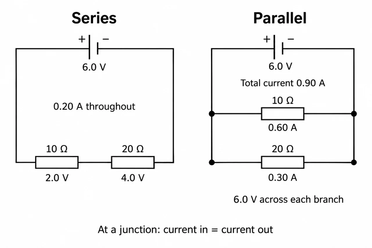
Image: illustration, not a documentary photograph. Original myAudience teaching concept; generated raster independently inspected. · Original generated teaching illustration; source facts attributed in the lesson.
Parallel branches and charge conservation
Parallel components connect between the same two junctions, providing separate routes. Each branch has the same potential difference because its ends connect to the same pair of points. Draw the junctions clearly and trace each route. The geometric position of a resistor on the page does not decide whether it is parallel; the connections do.
At a junction, total entering current equals total leaving current in a steady circuit. The supply current is the sum of the branch currents. Those currents need not be equal: at the same potential difference, the branch with lower resistance carries more current. If one parallel branch opens, other intact branches can still operate, assuming the supply continues to maintain its potential difference.
Adding a parallel resistor gives charge another conducting route. At the same supply potential difference, the original branch need not carry less current; instead the supply provides a larger total current. The overall resistance is therefore reduced and is smaller than the smallest branch resistance. the related topic does not require calculation of the combined resistance of two parallel resistors, so no reciprocal-resistance formula is required here.
Mixed circuits contain both arrangements. Identify two points joined by branches, then identify any component common to every route. Do not apply “same current” to different parallel branches or “same potential difference” to different series components. In a measurement circuit, the voltmeter branch is parallel with the component; its very small current is neglected in the ideal GCSE model.
Plate 02 compares the same two ideal fixed resistors on a supply maintaining 6.0 V. The parallel rails connect both ends of each branch to the same supply terminals; the four dots confirm the joins, and there is no empty-wire bypass. Branch currents of 0.60 A and 0.30 A add to 0.90 A. In 10 s, 6.0 C and 3.0 C enter the two branches while 9.0 C leaves the supply. Those are split flows of conserved charge, not newly created charge. Changing a branch can change total supply current even when the other branch’s potential difference is maintained.
The prediction that an existing branch is unaffected requires a supply maintaining the same potential difference. A real supply may drop its terminal voltage when extra current is demanded. In that case measure the new branch voltage and apply V/I at that condition; the parallel equal-voltage rule still holds, while the claim of unchanged current may fail.
Vocabulary: branch = separate circuit route; junction = point where routes meet; supply current = combined current before routes split; parallel = branches across the same two points.
Worked example: Two separate branches have currents of 0.24 A and 0.16 A. Both are across an ideal 6.0 V supply. Find supply current and state each branch’s potential difference.
Add the branch currents: 0.24 + 0.16 = 0.40 A.
Both ends of each branch connect to the same supply terminals.
Each branch therefore has 6.0 V across it.
Answer: Supply current 0.40 A; each branch 6.0 V.
Check your understanding: A 10 Ω branch initially has 6.0 V. After a 20 Ω parallel branch is connected, the measured terminal voltage is 5.0 V. Find both branch currents and the supply current. Does the first branch retain its old current?
Answer: 0.50 A and 0.25 A; total 0.75 A. The first branch falls from 0.60 A to 0.50 A.
Why: Both branches share the measured 5.0 V. Parallel topology guarantees equal branch voltage, not an ideal supply. The original unchanged-current prediction depended on maintaining 6.0 V.