This practical study: testing resistor combinations
By UK GCSE Physics · independent study · myAudience
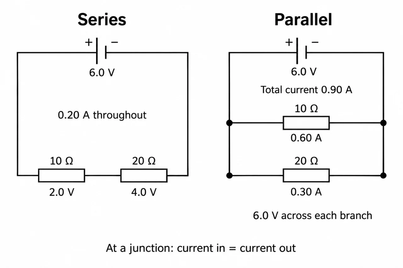
Image: illustration, not a documentary photograph. Original myAudience teaching concept; generated raster independently inspected. · Original generated teaching illustration; source facts attributed in the lesson.
This practical study: testing resistor combinations
The second part of the practical study compares resistors in series and parallel. First draw each arrangement with the same two known resistors. Mark the pair of terminals across which the combination is tested. This makes the comparison about connections rather than accidentally using a different component or measuring only part of the network.
With teacher-approved low-voltage apparatus, put the ammeter in the supply route and the voltmeter across the entire combination. Record total current and potential difference at a suitable operating condition. For series resistors predict the sum of their resistances. For parallel resistors predict a greater supply current at the same potential difference and an overall resistance below either individual resistance.
Disconnect the supply before rearranging components and ask for the circuit to be checked. Keep the resistor values, supply setting and temperature comparable. Ensure the parallel arrangement does not exceed component or meter current ratings. A source that cannot maintain its potential difference may give a lower voltage after an extra branch is connected; measuring V prevents that change from being mistaken for a failure of the circuit model.
Compare measured behaviour with the predictions, allowing for component tolerance and meter resolution. Recording supply current before and after adding a parallel branch tests the qualitative resistance claim without needing a parallel-resistance equation. Checking individual branch readings also tests current conservation. Reading these steps or calculating supplied data is practical reasoning, not evidence that apparatus skills have been demonstrated.
Plate 02 gives a conceptual series/parallel comparison, not a complete practical measurement circuit. To investigate a combination, A must measure the total supply current and V must span the whole combination. A voltmeter across only one series resistor cannot give the combination’s total resistance. Keep material, temperature and source conditions comparable, and measure actual voltage rather than assuming its setting is constant.
Vocabulary: component tolerance = allowed difference from nominal value; total current = current entering the whole network; fair comparison = deliberate change with relevant conditions controlled.
Worked example: Two nominal 20 Ω resistors in series have 4.0 V across the pair and measured current 0.10 A. In a separate parallel test at 4.0 V, each branch carries 0.20 A. Compare the supply currents.
Series prediction: 20 + 20 = 40 Ω and 4.0/40 = 0.10 A, agreeing with the reading.
Parallel total current = 0.20 + 0.20 = 0.40 A.
0.40/0.10 = 4, so the parallel arrangement takes four times the supply current in this ideal comparison.
Answer: 0.10 A in series and 0.40 A in parallel; the latter is four times greater.
Check your understanding: Two 20 Ω resistors are tested at a measured 4.0 V. Series supply current is 0.10 A; parallel supply current is 0.40 A. Explain the fourfold change, and decide whether two observed values prove temperature stayed constant.
Answer: Series has 40 Ω and parallel draws 0.20 A per branch, giving 0.40 A total. The readings alone do not prove temperature control.
Why: Series current is 4/40. Parallel branch currents are each 4/20 and add. Use temperature control, repeats and return-to-start tests as separate evidence; a numerical match cannot establish experimental competence.