Thermistors and LDRs as sensors
By UK GCSE Physics · independent study · myAudience
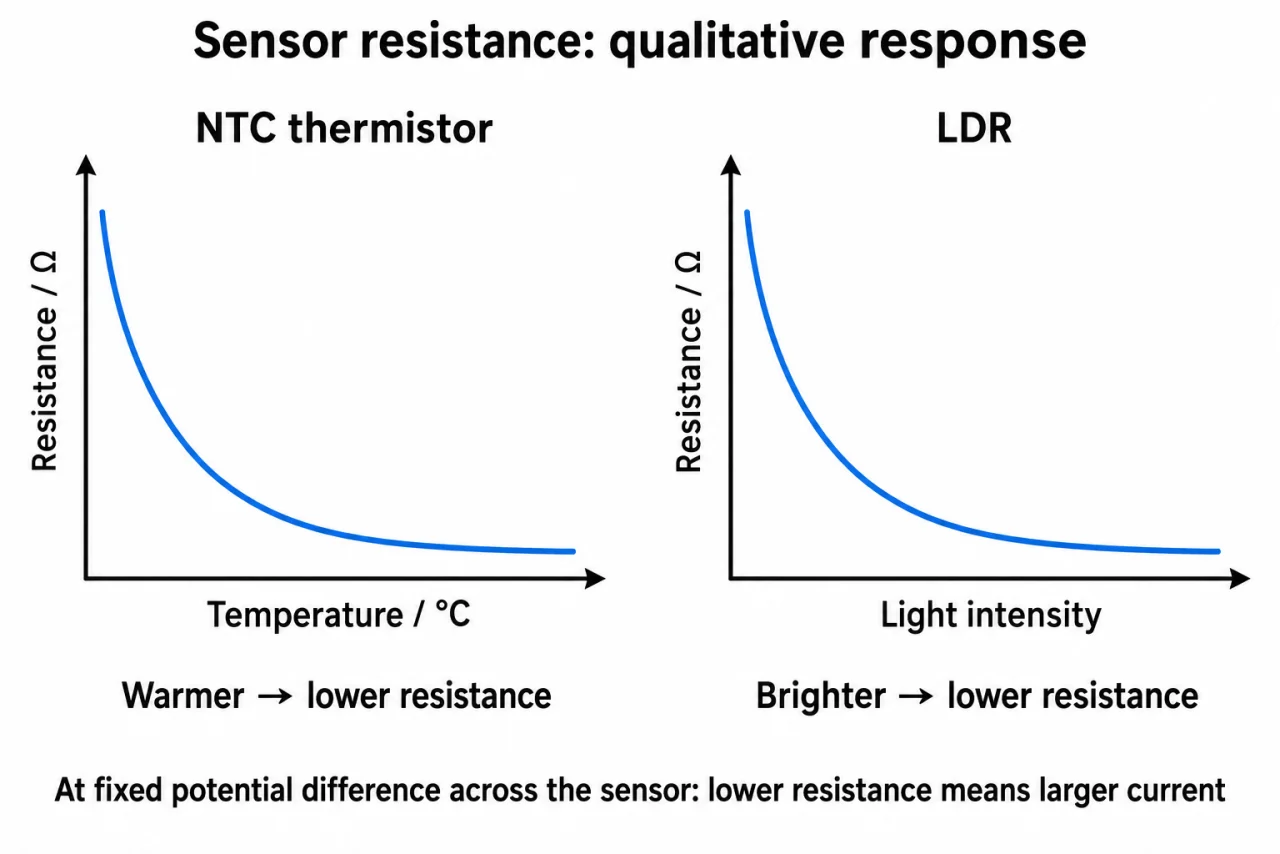
Image: illustration, not a documentary photograph. Original myAudience teaching concept; generated raster independently inspected. · Original generated teaching illustration; source facts attributed in the lesson.
Thermistors and LDRs as sensors
A sensor responds to its surroundings in a measurable way. The thermistor studied here has a resistance that decreases as its temperature rises. An LDR, or light-dependent resistor, has a resistance that decreases as light intensity rises. Neither change means a sensor creates a supply of energy: it changes the behaviour of a powered circuit.
In a simple test, measure the current through the sensor and potential difference across it, then calculate R = V/I for each condition. For a thermistor comparison, change temperature while keeping the measurement circuit comparable and allow the sensor to reach the chosen temperature. For an LDR comparison, change illumination while controlling its position and avoiding shadows from your hand. A lamp’s distance is a way to change illumination, not a direct measurement of light intensity.
A thermostat can use a thermistor response as an input to a control circuit that switches a heater. The design must make the falling resistance produce the desired action at the chosen temperature. Similarly, an automatic outdoor light can use an LDR so its larger resistance in darkness triggers a switch. Merely adding an LDR to a lamp in series does not guarantee that the lamp will become brighter in darkness; that simple arrangement tends to reduce current when resistance rises.
An optional way to understand a control signal is a sensor and fixed resistor in series across a fixed supply. Their potential differences share the supply. If the sensor resistance falls, the potential difference across it falls and that across the fixed resistor rises. Which pair of points the control circuit monitors matters. This uses series reasoning, not a new compulsory potential-divider formula. A complete control device needs a switching stage; a sensor alone is not a thermostat.
Plate 05 plots resistance vertically against temperature for an NTC thermistor and light intensity for an LDR. These are not I–V graphs. Both curves descend without reaching zero and have no numerical scale, so do not read a switching threshold or exact resistance from them. The temperature axis is in °C, but its unnumbered left end is not a claim of 0 °C or absolute zero. The footer holds potential difference across the sensor fixed. In a series control circuit that potential difference can change, so the whole circuit must be analysed before predicting the signal or lamp action.
For a fixed 6.0 V source, a 2.0 kΩ resistor and an NTC thermistor form one series route. If the NTC changes from 4.0 kΩ to 1.0 kΩ, total resistance falls from 6.0 to 3.0 kΩ, so current rises from 1.0 to 2.0 mA. The NTC drop falls from 4.0 to 2.0 V while the fixed resistor drop rises from 2.0 to 4.0 V. This follows ordinary series rules; a separate switching stage must still interpret the chosen signal.
Vocabulary: sensor = component responding to a condition; thermistor = temperature-dependent resistor; LDR = light-dependent resistor; control signal = circuit value used to decide an action.
Worked example: In a classroom sensor test at 3.0 V, current rises from 0.30 mA to 0.75 mA as a thermistor warms. Find the resistance at each condition.
Convert currents: 0.00030 A and 0.00075 A.
R_cool = 3.0/0.00030 = 10000 Ω.
R_warm = 3.0/0.00075 = 4000 Ω.
Answer: 10 kΩ when cooler and 4.0 kΩ when warmer.
Check your understanding: In that series sensor example, a controller activates above 3.0 V measured across the fixed resistor. Will warming activate it? Would monitoring the NTC give the same direction?
Answer: Warming activates the fixed-resistor signal, which rises from 2.0 to 4.0 V. The NTC signal instead falls from 4.0 to 2.0 V.
Why: The supply potential difference is shared. Which pair of points is monitored determines the control response; a sensor’s falling resistance alone does not specify a complete thermostat.