CPU components: work, control and communication
By UK GCSE Computer Science · independent study · myAudience
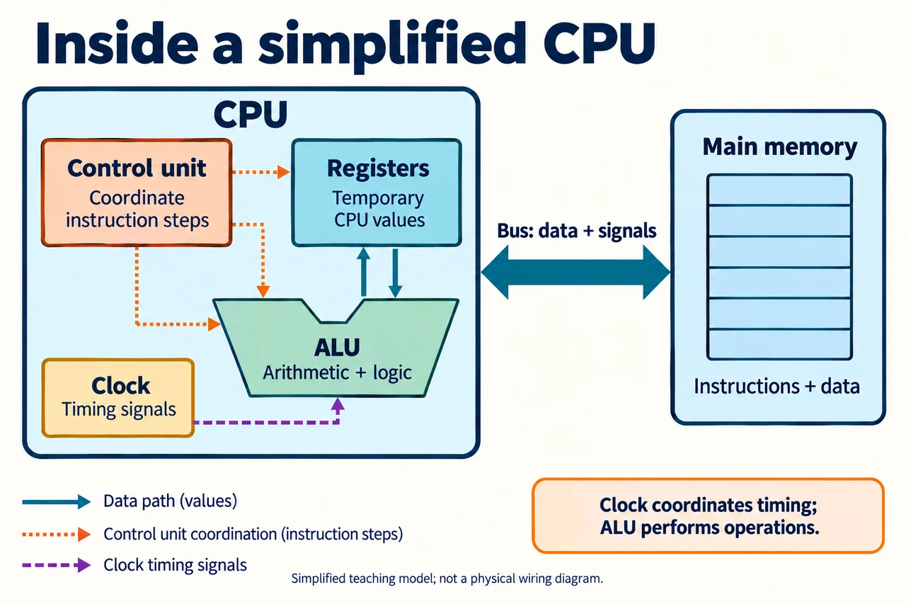
Original AI-generated teaching illustration via built-in image_gen; author inspected 2026-10-04. · Generated project artwork; no copied exam/publisher figure. Independent publication review pending.
CPU components: work, control and communication
A CPU executes instructions through cooperating components, not a single miniature person making decisions. The arithmetic logic unit performs arithmetic and logical operations. The control unit coordinates steps such as obtaining instructions and directing data movement. Registers provide small temporary storage within the processor. A clock supplies timing signals that help coordinate activity. A bus carries data or control signals between components. These roles answer different questions: what operation is performed, what coordinates it, where temporary values are held and how information is communicated.
The diagram uses a simplified CPU boundary and a separate main-memory box. The instruction and data path arrows are different from coordination arrows so that control is not confused with computation. An ALU can add two supplied values, but deciding that the current instruction requests addition is part of instruction interpretation and control. A register can hold an operand or intermediate result without itself performing the addition. A bus communicates information rather than storing an entire program as its primary role. Physical implementations are more complex than these boxes; the diagram is an explanatory model, not a wiring plan.
Suppose an instruction requires adding 7 and 5. Temporary values must be available to the operation, the ALU produces 12 and the result must go somewhere defined by the instruction. The control sequence coordinates these transfers. A later instruction might compare 12 with a limit, causing a logical result used to select subsequent behavior. Arithmetic and logic are therefore related processor work, whereas receiving a keystroke or saving a file involves additional system components and software. Explaining the ALU as everything the computer does erases important distinctions.
Registers are small, fast temporary CPU storage. current GCSE specification does not require names of particular registers. This lesson therefore uses generic operand and result values rather than asserting a required list of program counter, memory address register or accumulator names. Those can be useful optional enrichment in a specifically declared machine model, but real instruction sets and architectures need not match a single classroom layout. Likewise separate address, data and control bus classifications are optional explanatory extensions here, not an added mandatory assessed contract.
Clock frequency counts timing cycles per second. A 2 GHz fictional clock has two billion cycles per second, so one cycle lasts 0.5 nanoseconds because 1 divided by 2 billion seconds equals 0.5 billionths of a second. This conversion says nothing by itself about how many instructions finish per cycle or how long a complete task takes. Some work can span multiple cycles, wait for data or overlap other work. Calling every clock tick a completed instruction would make both the timing and the role description inaccurate.
Information must have a location and a meaning during a trace. Saying a value travels on the bus does not imply it stays there permanently; saying the CPU stores a temporary result does not imply the document has been saved to nonvolatile storage. Main memory can hold instructions and data needed for execution, while registers hold values currently useful inside the processor. The distinction is functional, not simply a larger box versus a smaller box. A causal answer follows the value through communication, temporary holding, operation and destination.
In an original trace, inputs 7 and 5 are made available to temporary CPU storage, a decoded addition directs the ALU, the ALU produces 12 and the result is retained for the next specified use. If a student swaps the register and ALU labels, the error is substantive: holding 7 is not the mechanism that adds 5. If they claim the clock selects the addition, they have substituted a timing role for instruction control. Correcting these explanations requires more than replacing a noun; explain why the component's role could or could not cause the observed change.
Transfer: a machine has correct input values but repeatedly uses subtraction when addition was requested. A fault in instruction decoding/control or incorrect instructions is a possible explanation; a working arithmetic circuit supplied the wrong operation could still calculate subtraction correctly. Conversely, an incorrect addition result despite the correctly selected operation could involve arithmetic hardware, corrupted operands or earlier software errors. Neither observation alone proves a specific component failure. A high-quality answer distinguishes operation selection from execution and states what further trace evidence would narrow the possibilities.
Worked example: Explain the roles needed to produce 12 from 7 and 5, then convert a fictional 2 GHz clock period.
Control coordinates the decoded addition; temporary registers provide values.
The ALU adds; communication paths carry values/results as required.
Period = 1/(2 × 10^9) s = 0.5 ns.
Answer: 12 is the arithmetic result; the clock period is 0.5 ns, not a guaranteed instruction completion time.
Check your understanding: A diagram labels the clock “adds values” and a register “transmits every signal between memory and CPU”. Correct both and explain the errors.
Answer: The ALU performs addition; the clock provides timing. Registers hold temporary CPU values; buses communicate data/signals between components. One component holding a value is not the same role as the communication route carrying it.
Why: Role distinctions must be justified through mechanisms; named-register knowledge is not required.