Trace instructions through fetch, decode and execute
By UK GCSE Computer Science · independent study · myAudience
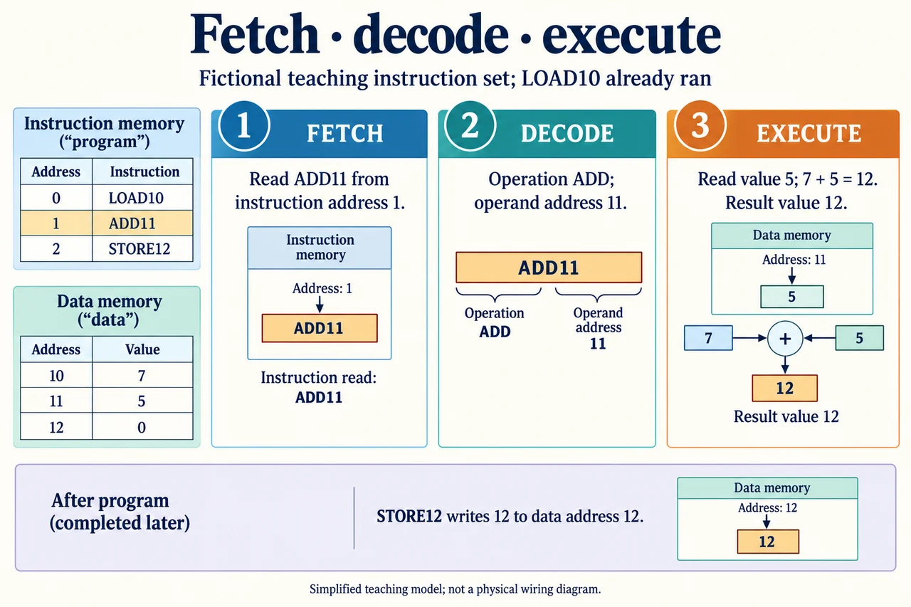
Original AI-generated teaching illustration via built-in image_gen; author inspected 2026-10-04. · Generated project artwork; no copied exam/publisher figure. Independent publication review pending.
Trace instructions through fetch, decode and execute
Fetching, decoding and executing explain how stored instructions lead to changes in state. Fetch brings the next instruction from main memory to the CPU. Decode determines the operation and relevant information encoded in that instruction. Execute carries it out, which can include reading or writing main memory. The cycle repeats for subsequent instructions. These are conceptual phases, not a guarantee of three clock ticks: modern processors can overlap work, while this GCSE teaching model intentionally follows a single instruction at a time.
Our fictional machine has a working-value register and memory addresses. Address 0 contains LOAD10, address 1 contains ADD11 and address 2 contains STORE12. Data address 10 initially holds 7, address 11 holds 5 and address 12 holds 0. LOAD copies the addressed data into the working value; ADD adds the addressed data to that value; STORE copies the value to the addressed memory location. These definitions make this invented trace executable and unambiguous. They are not an instruction set, not Python syntax and not a required architecture for every real processor. The separate instruction/data tables depict logical regions of our main memory, not a requirement for physically separate memory banks.
The first instruction is fetched from address 0. Decoding LOAD10 identifies loading as the operation and 10 as the operand address. Execution reads the value at address 10, namely 7, and places it in the working register. This is already two different kinds of memory access: obtaining an instruction from address 0 and obtaining its data from address 10. The digits in an address are not automatically the data value. Confusing address 10 with value 10 would produce the wrong trace even if the instruction word were copied correctly.
Next ADD11 is fetched from instruction address 1. Decode identifies an addition using the data at address 11. Execute obtains 5 and adds it to the current 7, leaving working value 12. The generated diagram focuses on this middle instruction after LOAD has already run. Its separate STORE note is essential: ADD has not, under our defined semantics, written 12 to data address 12. Instruction address 1, operand address 11 and resulting value 12 have distinct meanings, despite all being numbers in the same explanation.
Finally STORE12 is fetched from address 2 and decoded as a write to data address 12. Execution places the current working value 12 in that location. Data addresses 10 and 11 still hold 7 and 5 because none of these instructions changes them. The saved file on secondary storage has not automatically changed: STORE here means writing this teaching machine's main memory, not issuing a filesystem save. A precise trace states destinations, not merely that the result is stored somewhere. Original input values can remain available even after calculation.
We can test alternative inputs without changing the instruction sequence. If address 10 holds 4 and address 11 holds 9, the same program ends with working value and address 12 equal to 13. This separates program behavior from a particular data example. If the program instead fetches LOAD11 followed by ADD11, it doubles the value at address 11, because the first operand selection changed. The cause is the instruction sequence, not a failure of addition. Tracing one instruction at a time helps locate a conceptual or implementation error.
A deliberate aliasing variation changes the final instruction to STORE10. With original inputs 7 and 5, the result 12 overwrites data address 10, while address 11 remains 5 and address 12 remains 0. Repeating the program now loads 12 and adds 5, giving 17 before another STORE10. The second run differs because the program modified its own later input data. That does not mean it rewrote its instructions: addresses 0–2 remain unchanged. This example connects location, mutation and repeated execution without introducing a new assessed register-name requirement.
Transfer answers should distinguish state before, during and after execution. A student sees ADD11 and writes “the CPU adds 11, then automatically saves the file”. That answer conflates the operand address with its contents and main-memory computation with persistent storage. A justified correction reads the declared machine semantics: add 5 to the existing 7, hold 12, then only STORE12 writes 12 to main-memory address 12. Persisting a file requires other software and operations. This correction explains both mistakes and identifies the assumptions on which the result depends.
Worked example: Trace LOAD10, ADD11, STORE12 using the stated original data.
LOAD10 reads address10=7 into working value.
ADD11 reads address11=5, leaving working value12.
STORE12 writes12 to address12; addresses10/11 remain7/5.
Answer: Final main-memory data: 10→7, 11→5, 12→12. No secondary-storage save follows automatically.
Check your understanding: Change STORE12 to STORE10, then run the three instructions twice from original state. Give both results and justify why they differ.
Answer: First run writes12 to address10. Second run loads12 from that address and adds unchanged5 from address11, writing17 to address10. Address12 stays0 and instruction addresses0–2 remain unchanged.
Why: A correct answer traces the overwritten input and separates data mutation from instruction mutation or persistent saving.