A slit envelope and a grating order answer different questions
By UK A Level Physics · independent study · myAudience
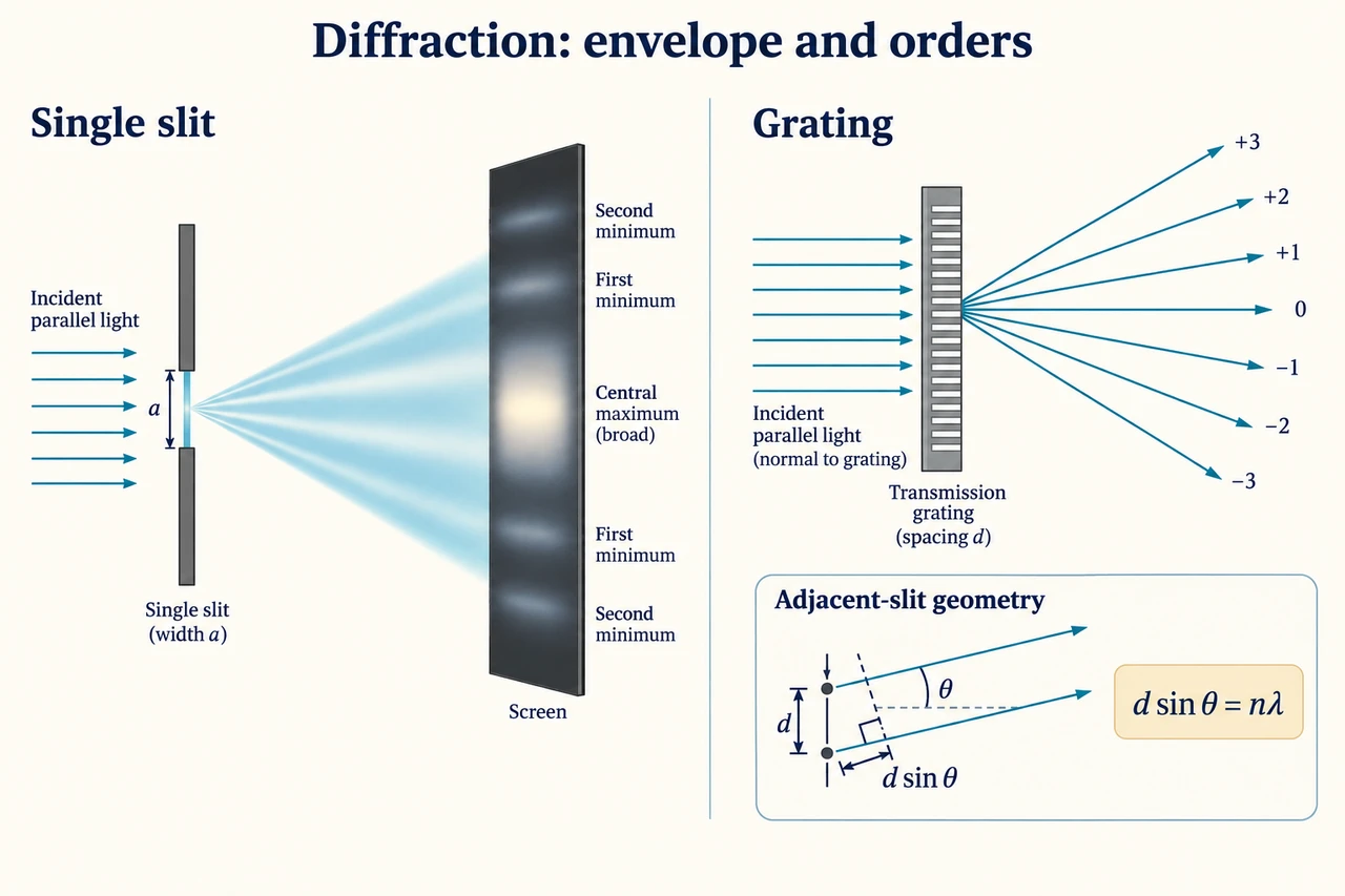
Image: illustration, not a documentary photograph. Single-aperture diffraction and a multi-slit grating solve distinct questions about spread and allowed angular orders. · Operator-authored generated illustration; scientific model and source limits reviewed separately.
A slit envelope and a grating order answer different questions
A wave spreading after an aperture is diffraction. Light passing through one narrow slit produces a broad central bright region with weaker side regions, rather than a sharp geometrical image of the opening. Contributions from different parts of the aperture reach a screen point with different phases and combine. That account explains why aperture size matters: diffraction is not simply a collision with one slit edge. Our single-slit discussion is qualitative, matching the specified treatment of central width. The image shows a schematic distribution and must not be measured to infer a wavelength or intensity law that has not been supplied.
For fixed wavelength and geometry, narrowing a single slit increases the angular width of the central maximum. Increasing wavelength also broadens it when the slit is unchanged. These are conditional comparisons; changing screen distance alters a physical screen width even when the angular spread stays the same. White light has overlapping component patterns, so its central region can be white while surrounding regions show colour separation. does not require the full intensity-versus-angular-separation graph here. We therefore explain the trend without making a memorised graph or an unintroduced numerical central-width formula stand in for understanding the aperture model.
A diffraction grating has many regularly spaced apertures or equivalent transmitting regions. Contributions from adjacent slits reinforce strongly in selected directions when their path difference is a whole number of wavelengths. Increasing the number of coherently illuminated slits sharpens the principal maxima in the simple model; it does not change their ideal angular positions if spacing and wavelength stay fixed. Grating spacing d means the separation between neighbouring slits, not the width of each individual slit. A slit envelope can modulate the strengths of orders, so an angular position allowed by the grating equation does not guarantee a detectable bright maximum in every apparatus.
For parallel light incident normally on a plane transmission grating, draw two adjacent outgoing parallel rays at angle θ to the forward normal. Their path difference is d sinθ. Reinforcement requires d sinθ = nλ, where the integer n identifies an order. The zero order has θ = 0; positive and negative orders lie on opposite sides. If incidence is not normal, the incoming paths already have an offset, and this simple relation needs modification. Defining the normal before drawing θ is essential: using the angle to the grating surface swaps the trigonometric relation and can produce a plausible but incorrect number.
A quoted line density must be converted into spacing. For 500 lines per millimetre, one millimetre contains 500 intervals in the ideal uniform grating, so d = 10⁻³/500 m = 2.0 × 10⁻⁶ m. This conversion is not 500 millimetres or the reciprocal 500 m⁻¹. Before using an inverse sine, check the dimensionless value nλ/d. Its magnitude cannot exceed one for a real direction in this model. An order requiring 1.20 is physically impossible, not a problem that can be fixed by switching the calculator from radians to degrees. At a limiting value of one the ray would be grazing; an algebraic bound alone is not proof that useful transmitted light can be observed there.
Different wavelengths generally produce different angles for the same nonzero order, which makes gratings useful for separating spectral lines. Higher orders can overlap wavelengths from lower orders, so a bright angle does not identify a unique wavelength without an order assignment or additional information. The earlier atomic-level lesson explained why a gas can emit discrete photon energies. A grating provides a way to separate their wavelengths, but it does not create those atomic levels or by itself prove which atom produced a line. Calibration, background and instrument response remain part of a real inference.
Single-slit width, two-slit fringe spacing and grating order angle are related wave phenomena with different geometries. The relation w = λD/s belongs to the small-angle two-source screen arrangement, while d sinθ = nλ describes normal-incidence grating directions. Substituting a screen distance into a grating equation or using line density where slit width belongs confuses the physical quantities. The changed example keeps the highest selected order at the same sine despite changing wavelength and spacing; that is a useful warning that an unchanged angle does not uniquely prove an unchanged wavelength.
This practical study includes interference through Young's slits and a diffraction grating. This lesson prepares the grating reasoning and source of possible misinterpretations; it does not establish spectrometer operation, which is not tested in this topic, or a performed practical. In the generated drawing, the spreading panel and the grating panel are separate models. Any ray angles are schematic unless numerical data are supplied in the text. A supervised real observation would need safe light-source arrangements and an explicit calibration method. Public teaching content must not turn a conceptual diagram into instructions to operate an unspecified laser or claim that a synthetic result is an experimental measurement.
Worked example: A plane transmission grating has 500 lines/mm and receives 600 nm light at normal incidence. Derive the spacing, find first- and third-order angles, determine the highest allowed integer order and explain what that limit does not guarantee.
Write the density as 500 lines within 0.001 m. The uniform spacing is d = 0.001/500 = 2.0 × 10⁻⁶ m. Keep d distinct from a slit width or a distance to the screen; those quantities can affect other features but are not the spacing in the order equation.
Convert wavelength to λ = 600 × 10⁻⁹ m. Normal incidence means the incoming wavefront reaches adjacent slits without a path offset. For an outgoing direction measured from the forward normal, adjacent-slit path difference is d sinθ, which must equal nλ at a principal maximum.
For n = 1, sinθ₁ = (600 × 10⁻⁹)/(2.0 × 10⁻⁶) = 0.30. Thus θ₁ ≈ 17.4576°. There are corresponding directions on either side; the negative-order direction has the opposite signed angle, not a negative wavelength.
For n = 3, sinθ₃ = 0.90 and θ₃ ≈ 64.1581°. This is much larger than the first-order angle, so a small-angle replacement of sinθ by θ would be poor here. Use the actual inverse sine rather than treating the order relation as a linear screen-distance formula.
The order bound is nλ/d ≤ 1, hence n ≤ d/λ = 3.333333…. The highest permitted positive integer is 3. For n = 4 the sine would be 1.20, so no real direction satisfies the stipulated normal-incidence model. Rounding 3.333 up to 4 would create an impossible order.
The angular condition is necessary for an ideal principal maximum; its brightness depends on illumination, the aperture envelope and detection. A permitted order can be weak or missing in an observation. The calculation does not establish that a real instrument detected every mathematically permitted order.
Answer: d = 2.0 μm; θ₁ ≈ 17.5° and θ₃ ≈ 64.2°. Highest allowed integer order 3, with symmetric negative orders. Allowed angle does not guarantee detectable intensity.
Check your understanding: Use a different grating with 1000 lines/mm and 450 nm light at normal incidence. Find the highest allowed order and its angle. A student says the unchanged angle proves the wavelength stayed unchanged, and that narrowing a separate single slit would move all grating orders. Evaluate both claims.
Answer: The new spacing is 0.001/1000 = 1.0 × 10⁻⁶ m. The bound d/λ = 1.0 × 10⁻⁶/(450 × 10⁻⁹) = 2.222222… allows highest order 2. Its sine is 2 × 450 × 10⁻⁹/(1.0 × 10⁻⁶) = 0.90, giving 64.1581°, the same angle as the previous third order. The ratio nλ/d is unchanged, not the wavelength. The two arrangements have different n, λ and d. Narrowing a separate single slit broadens its central diffraction feature; it does not change the spacing of the grating. If the width of the grating's own slits changes while their centres stay fixed, it can alter the envelope and order strengths while the ideal positions from d sinθ = nλ remain fixed.
Why: Identify the geometry and all factors in the ratio before inferring a cause from one angle. Distinguish a permitted direction from the envelope that sets its observed strength.