A fibre traps some rays but still broadens a pulse
By UK A Level Physics · independent study · myAudience
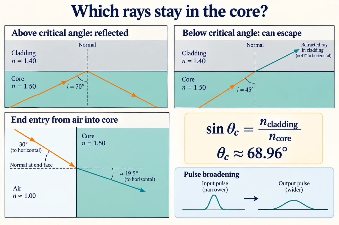
Image: illustration, not a documentary photograph. Normals determine refraction and total internal reflection at core and cladding boundaries. · Operator-authored generated illustration; scientific model and source limits reviewed separately.
A fibre traps some rays but still broadens a pulse
Refraction describes a change in propagation direction when a wave crosses a boundary and its speed changes. The refractive index of a material is n = c/v, with c the vacuum speed of light and v its phase speed in the material at the relevant frequency. Air is often approximated by n = 1 in these school calculations. At a stationary boundary the frequency stays the same, so wavelength changes with speed. Light slowing in glass does not lose frequency merely because a ray turns. Absorption, which transfers energy into the material, is a separate process from this change in direction and wavelength.
Draw a normal perpendicular to the boundary at the point where the ray crosses. Snell's law is n₁sinθ₁ = n₂sinθ₂, with both angles measured to that normal. Entering a higher-index medium generally bends the transmitted ray towards the normal; entering a lower-index medium bends it away. A ray along the normal changes speed without changing its direction. The angle to the surface is the complement of the angle to the normal, so silently swapping them gives a wrong sine even when a diagram looks convincing. Define which medium the ray starts in before deciding which index belongs on each side of the equation.
For a ray going from higher to lower index, increasing incidence eventually makes the refracted direction parallel to the boundary. At that critical angle θc, the refracted angle to the normal is 90 degrees, giving sinθc = n₂/n₁. For larger incidence angles, the simple ray model has no propagating refracted ray and gives total internal reflection. The condition requires n₁ > n₂ and incidence above the critical angle; a ray entering denser glass from air cannot be declared totally internally reflected at that first crossing. At smaller angles, reflection and transmission can coexist. The critical case itself is the limiting boundary, not an ordinary transmitted ray heading across the material.
A step-index optical fibre has a core with a higher refractive index than its cladding. Rays within the core can reflect at the core–cladding boundary when their incidence satisfies the condition. The cladding creates the controlled optical boundary; it is not merely decorative packaging. Geometry matters: at a flat end face the normal runs along the fibre axis, while at a straight side wall it runs across that axis. An internal ray angle of 19 degrees to the axis corresponds to about 71 degrees to the side normal in this two-dimensional model. Reusing the end-entry angle as the side incidence would misclassify which rays are guided.
Not every ray entering a fibre follows the same path. In a ray picture, an axial path is shorter than a zigzag path reaching the same output plane. The difference in transit times can spread an input pulse: this is modal dispersion. Real guided modes are wave solutions rather than independent little particles bouncing inside a pipe, so the drawing is an explanatory approximation. A simple path-length calculation can illustrate why delays differ, but it is not a prediction of every fibre's modal structure or rated bandwidth. Changing core dimensions, launch conditions or the index profile would require a model appropriate to those changes.
Material dispersion is a different source of broadening. Refractive index depends on frequency, so different frequency components of a pulse can have different group delays. A short pulse normally contains a range of frequencies; assigning one monochromatic phase speed to it does not automatically give the exact pulse-arrival time. Our geometric comparison deliberately stipulates a common propagation-speed approximation so its limitation is visible. Both modal and material effects can broaden pulses, but reducing one need not eliminate the other. This lesson stays with the specified step-index fibres; it does not extend the same diagram to graded-index designs or claim a particular commercial fibre's dispersion rating.
Absorption reduces the energy reaching the output by transferring some optical energy into the material. Pulse broadening instead concerns the distribution of arrival times; these effects can occur together, but they are not the same measurement. If neighbouring data pulses spread until they overlap, distinguishing them becomes harder and the useful signalling rate can be limited. A lower pulse height alone does not prove dispersion, and a wider pulse alone does not establish how much energy was absorbed. A receiver's bandwidth can also broaden a recorded signal. An honest explanation identifies which part is a propagation effect and which could come from source or detector behaviour.
The worked fibre is an invented numerical model with a straight core, flat entry face and stated indices. We use ray directions to test the critical-angle condition, then separately consider a geometric transit-time comparison. These are not measurements of a real cable or instructions for a live optical communications system. In the illustration, end-face and side-wall normals must be separate; the pulse insets are schematic and cannot be integrated to obtain power. The model shows why cladding and launch geometry matter while keeping dispersion, absorption and actual equipment performance distinct. Practical competence, assessment and complete qualification coverage remain open.
Worked example: A stipulated straight step-index fibre has ncore = 1.50 and ncladding = 1.40. Use c = 3.00 × 10⁸ m/s. Test an internal side-wall incidence of 70°. Then send a ray from air at 30° to the normal of the flat end face and test its side-wall incidence in the simple two-dimensional geometry.
The ray inside the core encounters a higher-to-lower index boundary, so a critical angle exists. Using the opposite ratio 1.50/1.40 would exceed one and would be the wrong assignment of incident and transmitted media, not evidence that the fibre lacks a critical condition.
Calculate sinθc = 1.40/1.50 = 0.933333…. Thus θc ≈ 68.9605°. The stipulated 70° side incidence is above that value, so the ray is totally internally reflected under this ideal boundary model. The comparison uses angles to the side normal.
The core phase speed is v = c/n = 3.00 × 10⁸/1.50 = 2.00 × 10⁸ m/s. At a stationary boundary frequency is unchanged; the wavelength becomes smaller by a factor 1/1.50 relative to vacuum. Neither relation claims that a broadband pulse has this exact group speed.
At the end face, approximate air index as 1. Snell's law gives sinθinside = sin 30°/1.50 = 1/3, so θinside ≈ 19.4712° to the horizontal end-face normal. It is not 19.4712° to the vertical side-wall normal.
For the straight rectangular cross-section in the drawing, side incidence is 90° − 19.4712° = 70.5288°. It exceeds 68.9605°, so this entry ray also satisfies the side-wall total-internal-reflection condition. Changing the core geometry would require checking this complement relation again.
The two tests describe directions, not the efficiency of launching real light or the number of guided modes excited. End-face reflection, absorption and wave effects are not quantified by this ray calculation. Keep the geometric conclusion separate from an unsupported claim about a cable's data rate or total transmitted power.
Answer: Critical angle≈68.9605°; the internal 70° ray is reflected. Core phase speed 2.00 × 10⁸ m/s. The 30° entry ray refracts to 19.4712° to the end normal, giving side incidence 70.5288° and satisfying the ideal condition.
Check your understanding: Change the core index to 1.46 and cladding to 1.44 while keeping a stipulated internal side incidence of 70°. Does it remain trapped? Separately assume an axial 1 km path and a ray at 60° to the axis share a teaching propagation speed of 2.00 × 10⁸ m/s. Find their path times and explain two limits of using that result to advertise bandwidth.
Answer: The new critical angle is arcsin(1.44/1.46) ≈ 80.5055°. Incidence 70° is below that threshold, so the ray is not totally internally reflected; it can have a transmitted component into the cladding. In the separate stipulated timing model, the axial path is 1000 m and takes 5.0 μs. A zigzag at 60° to the axis has length 1000/cos 60° = 2000 m and takes 10.0 μs, giving a 5.0 μs difference. This is a geometric comparison, not an automatically guided ray in the new-index fibre:60° to the axis would give 30° to its side normal and fail the trapping condition. The stipulated common speed also omits frequency-dependent group delay and the actual guided-mode structure. Pulse shape, launch conditions and receiver response matter, so neither that delay nor the critical angle alone supplies a rated network bandwidth.
Why: Recalculate the critical condition after changing indices and keep a separately stipulated path model from silently becoming a prediction of the changed fibre. Distinguish phase speed, group delay and equipment performance.