Choose the body before adding its forces
By UK A Level Physics · independent study · myAudience
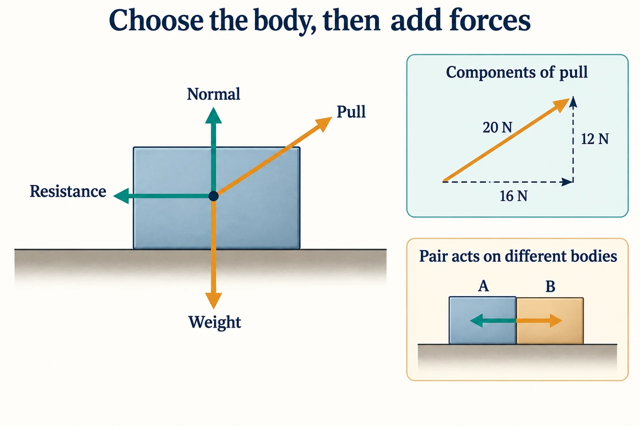
Image: illustration, not a documentary photograph. A free-body diagram and a separate component construction distinguish actual forces from their projections. · Operator-authored generated illustration; scientific model and source limits reviewed separately.
Choose the body before adding its forces
A force calculation begins by naming the body or system whose motion we want to explain. A free-body diagram contains the external forces acting on that body, not every force somewhere in the scene. For a block resting on a support, weight acts because of Earth's gravitational interaction and a normal force acts because of contact with the support. A pull and resistance may also act. The force the block exerts on the support belongs on the support's diagram, not as an extra arrow on the block. This boundary choice determines whether adding forces describes one object's acceleration or accidentally combines arrows from different objects.
Scalars have magnitude without direction; vectors have magnitude and direction. Mass and distance are scalars, while weight, displacement, velocity and acceleration are vectors. Speed is the magnitude of velocity, so an object can change velocity by changing direction without changing speed. A vector may be represented by signed components in chosen perpendicular directions. A negative component means opposite to the positive axis, not a negative magnitude of the complete vector. Label axes before assigning signs, and distinguish the length of an arrow used to represent a vector from a physical distance moved by the body.
For two perpendicular vectors, the resultant magnitude follows Pythagoras and its direction follows a stated angle convention. Components 12 N vertically and 16 N horizontally give 20 N in magnitude, but 20 N alone does not specify its direction. Resolve a force F at angleθ above the horizontal into Fx = Fcosθ and Fy = Fsinθ. The components replace the original vector in the sum; they are not additional physical forces to add alongside it. A scale drawing can represent sums at other angles. The specified numerical vector-addition demand is limited to two right-angle vectors, so a more complicated drawing should not quietly introduce an extra assessed calculation requirement.
An inclined plane provides a useful test of axes. Choose one direction along the plane and one perpendicular to it. For a plane at angleα to the horizontal, weight mg has magnitude mg sinα down the plane and mg cosα into it. The normal contact force is perpendicular to the surface, not automatically vertically upwards. If no other perpendicular forces act and acceleration perpendicular to the plane is zero, normal force is mg cosα. Additional pulls or contact constraints change that account. The angle labels refer to the plane and the chosen components; copying sine or cosine from memory without the diagram risks swapping the two contributions.
Newton's first law identifies equilibrium as zero resultant force: an object at rest remains at rest, and one already moving continues at constant velocity unless a resultant acts. Equilibrium does not mean the object must be stationary or that there are no forces. For two or three coplanar forces acting at a point, their vectors must close when placed head to tail; equivalently both perpendicular component sums vanish. A force board can investigate this condition, but the drawing alone is not evidence that the apparatus was used. A statement about point-force equilibrium also does not complete the separate rotational-equilibrium and moments topic. For an original point-force example,16 N right and 12 N up have a 20 N resultant. A third 20 N force directed exactly opposite that resultant closes the triangle and balances both components. A 20 N force with another direction would not do so merely because its magnitude matches. This three-force example is distinct from the worked block with four external forces.
Newton's second law relates resultant force to acceleration: Fresultant = ma for constant mass in this course model. The direction of acceleration follows the resultant, but it need not match the current velocity. A right-moving block with a leftwards resultant initially slows; it does not instantly move left. Vertical equilibrium and horizontal acceleration can occur simultaneously. On a horizontal support, an upward component of the pull reduces the normal force needed to balance weight. If the calculated normal would be negative, a support that can only push cannot supply it, and the maintained-contact assumption fails. The algebra is useful precisely because it exposes the boundary of the assumed model.
Newton's third law pairs forces from the same interaction acting on different bodies, with equal magnitudes and opposite directions. Earth's force on the block is paired with the block's gravitational force on Earth. The support's contact force on the block is paired with the block's contact force on the support. Weight and normal may balance in a special situation, but they are not each other's third-law partners: both act on the block and arise from different interactions. Internal third-law pairs can cancel in a combined-system force account, but that cancellation does not erase the acceleration or stress of each component considered separately.
Our worked block has a stipulated resistance rather than a friction law inferred from material labels. That distinction keeps the example within the qualitative friction scope and makes every numerical input visible. The illustration shows exactly four solid force arrows on the block and places dashed pull components in a separate construction. A real second-law investigation would need controlled mass, a force measurement and a defensible acceleration measurement, with calibration and timing limitations considered. Solving this invented case or drawing a correct pair does not demonstrate performed practical skills, assessed mastery or engineering safety. The model is a tool for reasoning about forces and contact, not a certification of an actual mechanism.
Worked example: A 2.0 kg block remains in contact with a horizontal support. It is pulled by 20 N at arctan(3/4) above the horizontal, with a stipulated 6 N opposing horizontal resistance. Use g = 9.8 m/s². Find pull components, normal force and horizontal acceleration; distinguish equilibrium from a third-law pair.
Choose the block as the body and right/up as positive axes. The external forces are weight down, normal up, angled pull and resistance left. The support force exerted by the block is not added to this free-body diagram because it acts on the support.
The pull direction gives a 3–4–5 triangle: cosθ = 4/5 and sinθ = 3/5. Thus Fx = 20 × 4/5 = 16 N and Fy = 20 × 3/5 = 12 N. These two components replace the original 20 N vector when calculating sums.
Weight is mg = 2.0 × 9.8 = 19.6 N down. With maintained contact and zero vertical acceleration, N + 12 − 19.6 = 0, giving N = 7.6 N. Setting N equal to 19.6 N would neglect the pull's upward contribution.
Horizontal resultant is 16 − 6 = 10 N rightwards. For constant mass, a = Fresultant/m = 10/2.0 = 5.0 m/s². Vertical equilibrium does not imply zero horizontal resultant, so this block is not in complete translational equilibrium.
As a separate component check, √(16² + 12²) = 20 N and tanθ = 12/16 = 3/4. The reconstructed vector matches the pull, but it is still one physical force. Adding 20 N again to the component sum would count the same interaction twice.
Weight and normal are not a third-law pair even if they happened to be equal. Their partners act on Earth and on the support respectively. Here they are not even equal in magnitude; vertical balance is achieved by normal plus the upward pull opposing weight.
Answer: Pull components 16 N right and 12 N up; normal 7.6 N; horizontal acceleration 5.0 m/s² right. Weight and normal act on the same body and are not a third-law pair.
Check your understanding: Change the pull to 15 N at arctan(4/3), and stipulate 11 N horizontal resistance while the block is moving right. Keep mass and g unchanged. Find the acceleration and normal force, then explain what fails if a new upward pull component exceeds the weight. As an inclined-plane check, resolve the same block's weight on a 30° plane with no other perpendicular forces.
Answer: The new pull has horizontal 15 × 3/5 = 9 N and vertical 15 × 4/5 = 12 N. Normal remains 19.6 − 12 = 7.6 N. Horizontal resultant is 9 − 11 = −2 N, giving a = −1.0 m/s²: the initially right-moving block slows, rather than instantly reversing. If the upward pull exceeds 19.6 N, the maintained-contact equation demands a negative normal. A support that can only push cannot provide that, so the block loses contact and the vertical-equilibrium assumption must be replaced by a motion calculation. On the 30° plane, weight has component 19.6 sin 30° = 9.8 N down the plane and 19.6 cos 30° ≈ 16.974 N into it. With no other perpendicular forces and no perpendicular acceleration, the normal is about 17.0 N, not 19.6 N.
Why: Resolve the actual force direction, sum forces on one body and interpret acceleration separately from velocity. A failed contact assumption and a changed axis system require explicit physical reasoning, not only new substitutions.