Changing voltage without connecting the coils
By How things work · myAudience
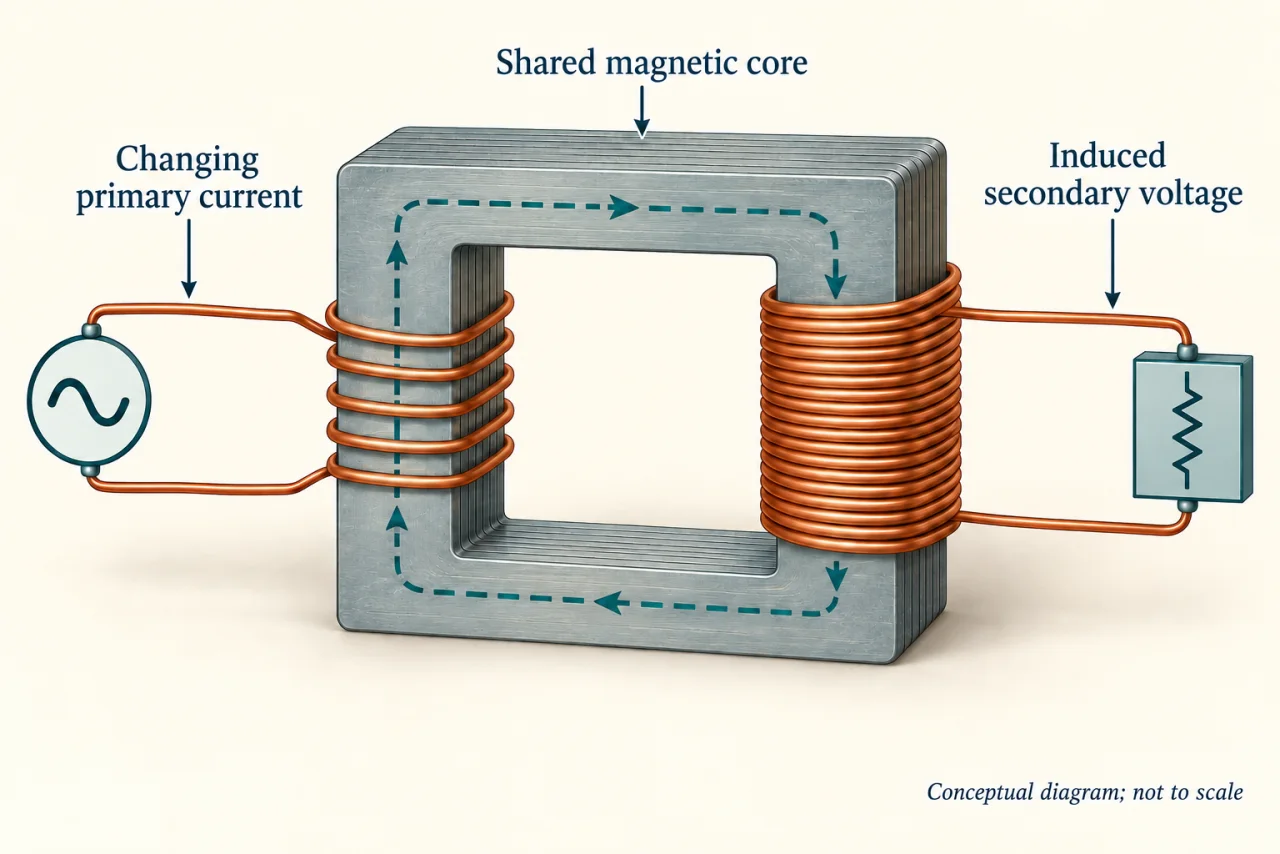
myAudience original rendered teaching illustration. Image: illustration, not a documentary photograph. · Operator-authored generated illustration; scientific model reviewed separately.
Changing voltage without connecting the coils
A transformer uses a changing magnetic field to link two windings. An alternating current in the primary winding produces changing magnetic flux through the core. That changing flux induces a voltage in the secondary winding. The basic model is magnetic coupling, not current jumping directly from one wire to the other.
For an ideal transformer sharing the same changing flux, the voltage ratio equals the turns ratio: secondary voltage divided by primary voltage equals secondary turns divided by primary turns. This model assumes negligible losses and appropriate coupling. Ordinary transformers do not provide a continuous transformed output from a steady direct-current input.
Power is not multiplied for free. In the ideal loaded model, an increase in voltage corresponds to a decrease in current for the same transferred power. Real devices also have winding resistance and magnetic losses. Cooling and insulation are part of their design.
In an invented model, a primary has 100 turns and a secondary has 500 turns. With 12 V AC at the primary, the ideal secondary voltage is 12 × 500/100 = 60 V. If the model transfers 120 W, primary current is 10 A and secondary current is 2 A. AC voltages and currents here are RMS values; the load is idealised as resistive, with negligible transformer losses.
The public purpose matters too: voltage transformation helps electricity travel and become usable locally. Access requires sound infrastructure and ongoing maintenance, not merely a one-off equipment donation.
Discuss: should a town extend reliable electricity first to a clinic, remote homes or local businesses? Explain how urgency, equal access and long-term benefit support different priorities. Ask who has a voice in the decision; voltage ratios alone cannot settle it.
Image: illustration, not a documentary photograph.
Worked example: An ideal transformer has 100 primary turns and 500 secondary turns. The input is 12 V AC and transferred power is 120 W. Find secondary voltage and currents.
Turns ratio = 500 ÷ 100 = 5; secondary voltage = 12 × 5 = 60 V.
Primary current = 120 ÷ 12 = 10 A.
Secondary current = 120 ÷ 60 = 2 A. AC values are RMS; assume a resistive load and negligible transformer losses.
Answer: 60 V AC, 10 A primary current and 2 A secondary current.
Check your understanding: An ideal transformer has 400 primary turns, 100 secondary turns and 24 V AC input. Predict its secondary voltage; does this mean energy disappears?
Answer: 24 × 100/400 = 6 V. Voltage decreases, but ideal power conservation permits greater secondary current for a given transferred power. A real transformer also dissipates some input energy.
Why: Use the declared system boundary and conserve energy, mass or atoms. The worked example explains the calculation; these are invented teaching values.