High voltage: a smaller current for the same transfer
By How things work · myAudience
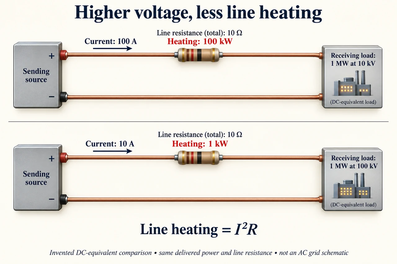
myAudience original rendered teaching illustration. Image: illustration, not a documentary photograph. · Operator-authored generated illustration; scientific model reviewed separately.
High voltage: a smaller current for the same transfer
A transmission network links generation to distant users. Transformers change AC voltage at different stages; overhead lines and cables carry electrical energy, and substations route and protect the network. The technology is not simply a longer domestic wire. Higher voltage permits a smaller current for a specified transferred power under a stated circuit model, which can reduce resistive heating in the conductors.
The plate compares two deliberately simplified DC-equivalent circuits, not a wiring plan for a real three-phase AC grid. Each has a source, a line modelled by the same total loop resistance, and a receiving load. The high-voltage model needs less current for the same receiving power. Two conductors close each circuit: a lone outgoing wire is not a complete steady circuit. The plate labels receiving voltage, current and line heating; sending voltage and the line voltage drop are calculated in the written example below.
Start with receiving power P = Vr I. With fixed P, current I = P/Vr. Line heating is I²R, so increasing receiving voltage by a factor k reduces current by k and resistive heating by k² if R is unchanged. That conclusion depends on holding delivered power and resistance constant. It does not imply all grid losses follow that ratio: transformers, AC reactive effects, insulation, equipment limits and load pattern introduce other terms.
In an invented 1 MW receiving load at 10 kV, current is 100 A. A 10 Ω total line resistance dissipates 100 kW, and its voltage drop is IR = 1 kV, so sending voltage is 11 kV. Receiving 1 MW at 100 kV needs 10 A; the same line dissipates 1 kW and drops 100 V, so sending voltage is 100.1 kV. Sending powers are 1.1 MW and 1.001 MW. Using the receiving voltage while calling it the sending voltage would quietly break the energy account.
Higher voltage requires suitable insulation, clearance, switchgear and protection; these are engineered systems, not a home experiment. A line route may improve access to renewable generation while affecting landscapes, land rights and communities. Discuss what evidence should decide between an overhead route, underground connection or demand reduction. Cost alone cannot represent every impact, and a buried cable has different engineering limits rather than zero environmental burden.
For a transfer test, compare a proposed doubled voltage with a doubled conductor resistance. At unchanged delivered power, current halves; heating becomes (1/2)² × 2 = 1/2 of the original. The voltage drop IR stays unchanged because one factor halves and the other doubles. Thus a reduced heating loss does not always mean an equally reduced voltage drop. This established mechanism is the starting point for, rather than a substitute for, AC network stability and protection studies.
Image: illustration, not a documentary photograph.
Worked example: For an invented DC-equivalent receiving load of 200 kW at 20 kV, total line R = 5 Ω. Find current, heating, sending voltage and sending power.
I = 200,000/20,000 = 10 A.
Line heating = 10² × 5 = 500 W; voltage drop = 10 × 5 = 50 V.
Sending voltage = 20,050 V; sending power = 200,500 W.
Answer: 10 A; 500 W heating; 20.05 kV sending voltage; 200.5 kW sending power.
Check your understanding: At unchanged delivered power and line resistance, receiving voltage triples. What happens to current, heating and voltage drop?
Answer: Current becomes one third, resistive heating one ninth, and voltage drop one third. These follow I = P/Vr, loss = I²R and drop = IR under the stated DC-equivalent model.
Why: Declare the system boundary and assumptions before applying conservation. Invented values test reasoning, not a real installation.