The thin film that carries a machine
By How things work · myAudience
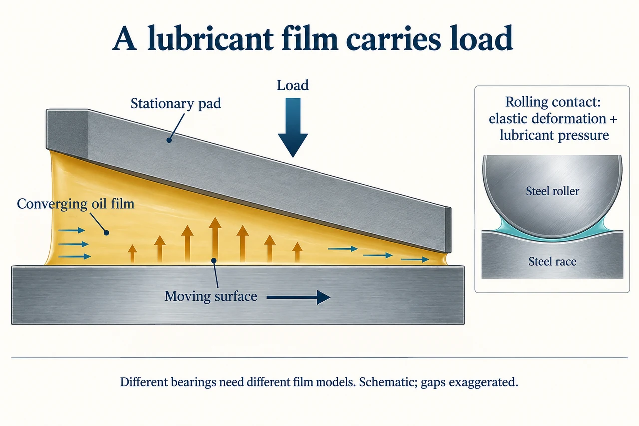
myAudience original rendered teaching illustration. Image: illustration, not a documentary photograph. · Operator-authored generated illustration; scientific model reviewed separately.
The thin film that carries a machine
A bearing supports a load while allowing relative motion. A sliding bearing and a rolling-element bearing do that in different ways. Lubrication is not simply making everything slippery: a film must separate surfaces while accommodating load and motion, and its behaviour depends on geometry, speed, temperature, lubricant supply and contamination. A clean-looking machine can still have damaging contacts that are far too small to see.
The large drawing shows one ideal hydrodynamic sliding-pad model. The lower surface drags viscous oil into a narrowing gap beneath a stationary pad. Flow cannot pass through that narrowing space unchanged, so a pressure distribution develops in the film. Its resultant supports the applied load. The wedge is exaggerated for visibility; it is not a ball-bearing contact or a recommended assembly. A separate small contact model introduces rolling bearings, where elastic surface deformation and pressure-dependent lubricant behaviour become important. Do not transfer a simple sliding-pad formula to a rolling contact.
Film formation does not remove every loss. Oil layers move at different speeds and shear one another. In the deliberately simpler parallel-plate model, the resisting force is F = viscosity × area × speed / gap. This model assumes a Newtonian liquid, uniform separation, steady laminar motion, negligible pressure-driven flow and no slip at the two surfaces. It estimates shear drag; it does not calculate the pressure supporting the tilted pad. That distinction matters: solving the easy drag equation does not prove a bearing will carry its load.
Grease in rolling bearings supplies lubricant to the contacts, but its supply can become inadequate. SKF describes replenishment, losses and eventual film breakdown, and warns that excessive grease can increase churning and temperature. This is evidence against the idea that more grease always means less friction. Manufacturer evidence is specific to the tested bearing and lubricant systems; it is not permission to choose maintenance intervals from this illustration.
Use the original numerical model to expose a design tension. For viscosity 0.06 Pa·s, sheared area 0.002 square metres, speed 2 m/s and gap 0.00004 m, the predicted drag is 6 N. Maintaining that motion takes 12 W against this drag. If viscosity halves with temperature while geometry and speed stay fixed, the model predicts 3 N and 6 W. Lower drag alone cannot justify hotter operation: a different load-support calculation and the actual film condition still have to be assessed. Energy saved in one loss channel is not evidence that the system is safe.
An engineer comparing lubricants must ask what failures the simplified model omits: particles can damage contacts, supply can fail, and real viscosity changes with conditions. The correct response to an unexpectedly hot or vibrating machine is qualified diagnosis and manufacturer guidance, not reaching into moving equipment. Evaluate a proposal using reliability, lubricant disposal, maintenance access and worker exposure as well as power consumption. A low-price lubricant that shortens equipment life may increase waste and disproportionately burden the people maintaining it.
Image: illustration, not a documentary photograph.
Worked example: In the stated parallel-plate model, calculate drag and power for viscosity 0.06 Pa·s, area 0.002 m², speed 2 m/s and gap 40 micrometres.
Convert the gap: 40 micrometres = 0.00004 m. Pa·s × m² × m/s ÷ m has units N.
F = 0.06 × 0.002 × 2 / 0.00004 = 6 N.
P = Fv = 6 × 2 = 12 W. This is shear-drag power in a teaching model, not total machine loss or a load-capacity calculation.
Answer: 6 N drag; 12 W shear-drag power under the declared assumptions.
Check your understanding: For the same model, both speed and gap double. Predict drag and power. A supplier then claims that lower viscosity must improve bearing safety; assess the reasoning.
Answer: Speed/gap is unchanged, so drag remains 6 N. Power doubles to 6 × 4 = 24 W because the unchanged resisting force acts at twice the speed. Lower viscosity reduces the simple shear term but this model does not predict load capacity, mixed contact or lubricant degradation. Require evidence for the real bearing and operating conditions before claiming safety.
Why: Keep shear drag, pressure-supported load and actual failure evidence separate. Doubling speed does not leave power unchanged even when drag is unchanged.