Compressed air is a spring as well as a supply
By How things work · myAudience
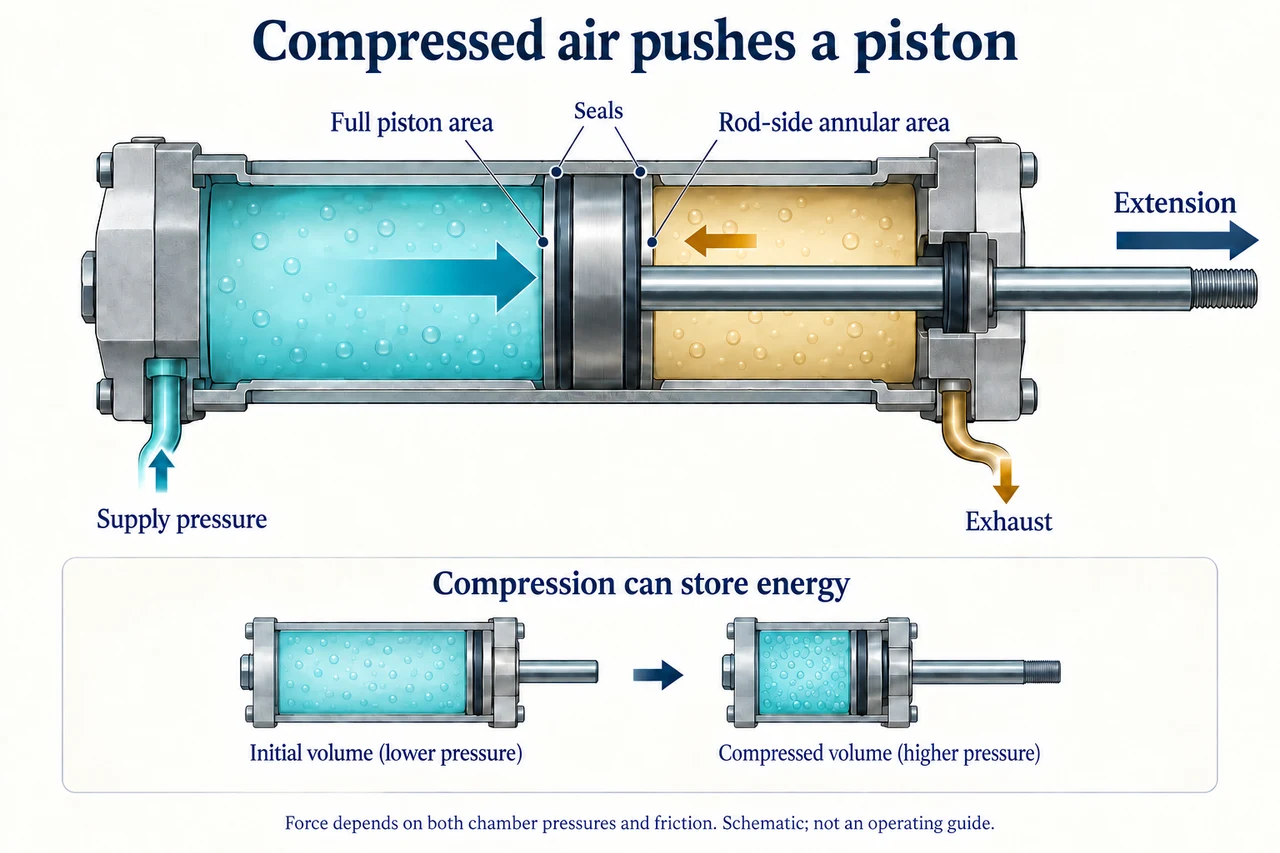
myAudience original rendered teaching illustration. Image: illustration, not a documentary photograph. · Operator-authored generated illustration; scientific model reviewed separately.
Compressed air is a spring as well as a supply
A pneumatic cylinder converts pressure differences into mechanical force and motion. In a double-acting cylinder, air can act on either side of a sealed piston. The rod occupies some area on its side, so equal chamber pressures do not necessarily give equal opposing forces. The cutaway shows extension: the left chamber receives supply air and the rod-side chamber exhausts. Pressure acts on both piston faces; net force also has to overcome friction and the external load.
For a conceptual cylinder with piston area A and rod area a, the left face has area A while the right face has area A − a. Using gauge pressures pL and pR relative to the same surrounding atmospheric pressure, the ideal extension force is pL A − pR(A − a). This assumes the exposed rod end experiences the reference atmosphere and neglects seal friction and acceleration. With absolute pressures the atmospheric contribution at the rod must also be included. Mixing gauge and absolute values in the two chambers produces a wrong answer.
Air is compressible: changing its volume can change its pressure and store energy. Consequently a piston may move while chamber pressures are still changing. An ideal sealed sample at fixed temperature satisfies pV = constant, with absolute pressure, not gauge pressure. This is a separate thought experiment, not a complete flowing-cylinder model; filling, exhaust, temperature changes and moving seals need additional information. Comparing pneumatic and hydraulic actuators should therefore distinguish force capacity from stiffness, response and control, rather than declaring one universally superior.
In the picture, follow the supply and exhaust ports separately. The larger rightward face-force arrow and smaller opposing arrow explain the net extension; they do not specify a calibrated pressure. The small inset shows a sealed air sample compressed to a smaller volume. It is not a second instruction to connect a cylinder, and it does not imply that pressure remains constant during compression. Real compressed-air assemblies can retain dangerous stored energy after a power switch is opened.
An original force example uses full area 0.001 m², rod area 0.0002 m², left gauge pressure 500,000 Pa and right gauge pressure 100,000 Pa. Left force is 500 N; right opposing force is 80 N. The ideal net is 420 N. If measured seal resistance is represented by 30 N opposing extension, only 390 N remains before acceleration and other effects. A 450 N external resisting load therefore cannot be overcome in the proposed steady extension model. Increasing a label saying rated pressure cannot fix missing evidence about actual pressure at the cylinder.
Festo recommends selecting the actuator for the application and considering the complete compressed-air system when evaluating energy. That includes supply generation and preparation, not only work at the cylinder. A design argument should compare controllability, reliability, leaks, maintenance, noise and lifecycle costs. Teaching the mechanism does not qualify a learner to assemble or depressurise equipment; trained personnel must follow the applicable design and isolation procedures. Shared access to reliable maintenance and safe work conditions belongs in the decision, not only purchase price.
Image: illustration, not a documentary photograph.
Worked example: Find the ideal extension force for A = 0.001 m², rod area a = 0.0002 m², pL = 500 kPa gauge and pR = 100 kPa gauge. Then allow 30 N opposing seal friction.
Rod-side annular area = 0.001 − 0.0002 = 0.0008 m². Convert kPa to Pa.
Left force = 500,000 × 0.001 = 500 N. Opposing right force = 100,000 × 0.0008 = 80 N.
Ideal net = 500 − 80 = 420 N; allowing the specified seal friction gives 390 N before load and acceleration.
Answer: 420 N ideal extension force; 390 N after the specified friction allowance.
Check your understanding: Both chambers are at 500 kPa gauge. What ideal net force results? Separately, a sealed air sample is compressed isothermally from 300 cm³ at 200 kPa absolute to 200 cm³. Find its final absolute and gauge pressures for ambient pressure 100 kPa.
Answer: Equal chamber gauge pressures give 500,000 × (0.001 − 0.0008) = 100 N towards extension, not zero, because the areas differ. For the sealed sample, final absolute pressure = 200 × 300/200 = 300 kPa. Final gauge pressure = 300 − 100 = 200 kPa. The isothermal sample calculation does not describe the open supply/exhaust cylinder in the picture.
Why: Use the declared effective areas and common pressure reference. The ideal-gas pressure-volume relation requires absolute pressure and a separate sealed, constant-temperature boundary.