How an electric motor produces torque
By How things work · myAudience
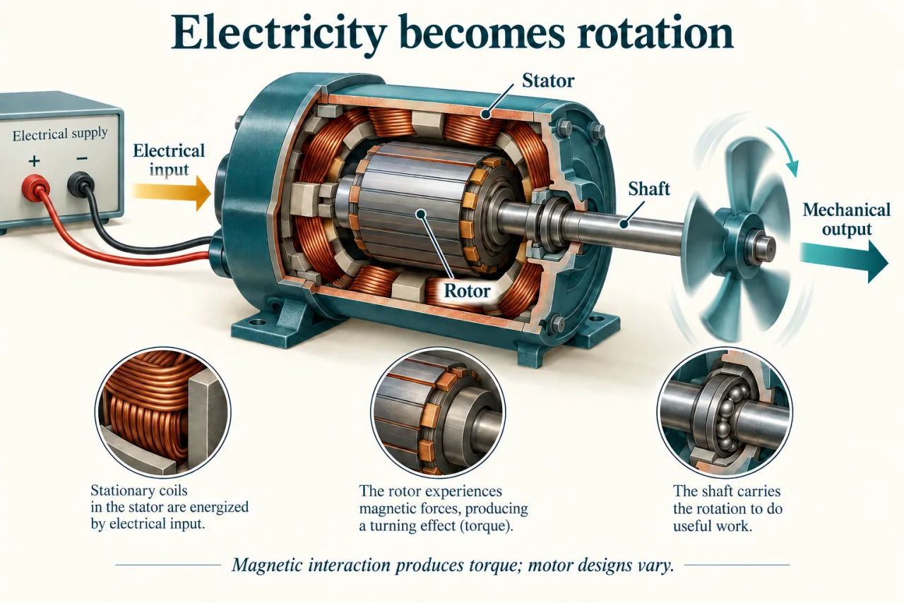
myAudience original rendered teaching illustration. Image: illustration, not a documentary photograph. · Operator-authored generated illustration; scientific concept model reviewed separately.
How an electric motor produces torque
An electric motor converts electrical input into mechanical output through electromagnetic interaction. Torque is a turning effect: it can accelerate a rotor or balance a resisting load. Rotation is useful because a shaft can drive a fan, pump or transmission. The energy still comes from the electrical supply; a magnet or a carefully shaped rotor does not create an unlimited source of power.
In the cutaway, the stator is the stationary surrounding structure, the rotor is the moving inner assembly, and the shaft carries rotation to a fan. The smaller insets distinguish these parts. The drawing explains the energy path and component roles; it omits detailed commutation, power electronics and winding connections. Do not infer that connecting a fixed supply directly to any illustrated coil arrangement would make a functioning motor.
A current-carrying conductor in a magnetic field can experience a force. A suitable arrangement makes these forces produce torque around an axis. Continuous rotation requires the magnetic interaction to remain appropriately coordinated with rotor position: different motors accomplish this with different physical and electronic arrangements. Permanent-magnet, induction and reluctance machines should not be collapsed into one universal winding recipe. The rotor-stator distinction applies broadly, while their internal mechanisms differ. The motor torque must also be considered against the load torque. A positive difference can accelerate the combined rotor and load; at a steady operating point their torques balance. Thus a motor with adequate power at one speed may still fail to start a demanding load. The illustration identifies components but supplies no torque-speed curve or permissible thermal operating envelope.
For a steady shaft rotating at angular speed ω in radians per second, mechanical power is torque τ multiplied by ω. The relation follows from work: a small angular movement dθ against torque τ transfers work τdθ; dividing by time gives τdθ/dt = τω. Newton-metres describe torque and watts describe power. They are related but not identical measurements. A stationary shaft can have torque while useful rotational power at that instant is zero.
Efficiency compares the mechanical-output and electrical-input boundaries. If the motor supplies 200 W mechanically from 250 W electrically, the ratio is 0.80. The remaining transfer includes heating and other losses; energy has not disappeared. When the load changes, speed, torque, current, heating and efficiency can all change. An output reading at one operating point is not a promise of the same performance everywhere. Separate the controller from the motor when tracing losses: grid-to-shaft efficiency is controller efficiency multiplied by motor efficiency under the assumed operating conditions. A centrifugal fan can be modeled, within suitable similarity assumptions, with load torque proportional to speed squared. Combining that load rule with P = τω gives power proportional to speed cubed. This relationship belongs to that load model, not to every machine attached to a motor.
Motors are established technologies; particular magnet substitutions, cooling methods and geometries require their own evidence. DOE research material explains rotor and stator roles but its forecasts and comparative performance statements are not adopted as current universal rankings. For a whole motor-driven system, consider the motor, controller, mechanical load and duty cycle together. Improving a component while wasting power in the connected process can miss the larger opportunity.
Discuss: an efficient motor uses costly materials whose extraction has social and environmental impacts. Compare lifetime energy savings, supply-chain conditions, repairability and alternative designs. Explain what operating lifetime and electricity evidence you would need before recommending the purchase.
Image: illustration, not a documentary photograph.
Worked example: A modeled fan needs 2 N·m at 100 rad/s. Assume fan torque is proportional to speed squared, motor efficiency is 80%, and controller efficiency is 90%, both constant over this example. Find supply power at full speed and at half speed. What percentage reduction does the model predict?
At full speed, shaft power = 2 × 100 = 200 W.
Supply power = 200 ÷ (0.80 × 0.90) = 277.78 W.
At half speed, torque = 2 × (50/100)² = 0.5 N·m; shaft power = 0.5 × 50 = 25 W.
Supply power = 25 ÷ 0.72 = 34.72 W, or one eighth of the modeled full-speed input.
Reduction = (1 − 1/8) × 100% = 87.5%. This comparison also reduces fan service; it is not the same airflow at lower cost.
The result assumes the specified load scaling and constant efficiencies. Real operating curves and the required process duty must be checked before adopting it.
Answer: Approximately 277.8 W versus 34.7 W: an 87.5% modeled reduction while providing reduced fan service.
Check your understanding: Would half speed also require one eighth of shaft power for a conveyor whose resisting torque remains constant? Explain using the mechanism, not a memorized savings rule.
Answer: No. With constant torque, P = τω makes shaft power proportional to speed; halving speed halves shaft power under that model.
Why: The cubic fan result combines a square-law torque relation with rotational power. A different load law changes the conclusion. Electrical input also depends on efficiencies.