Gears exchange speed for torque
By How things work · myAudience
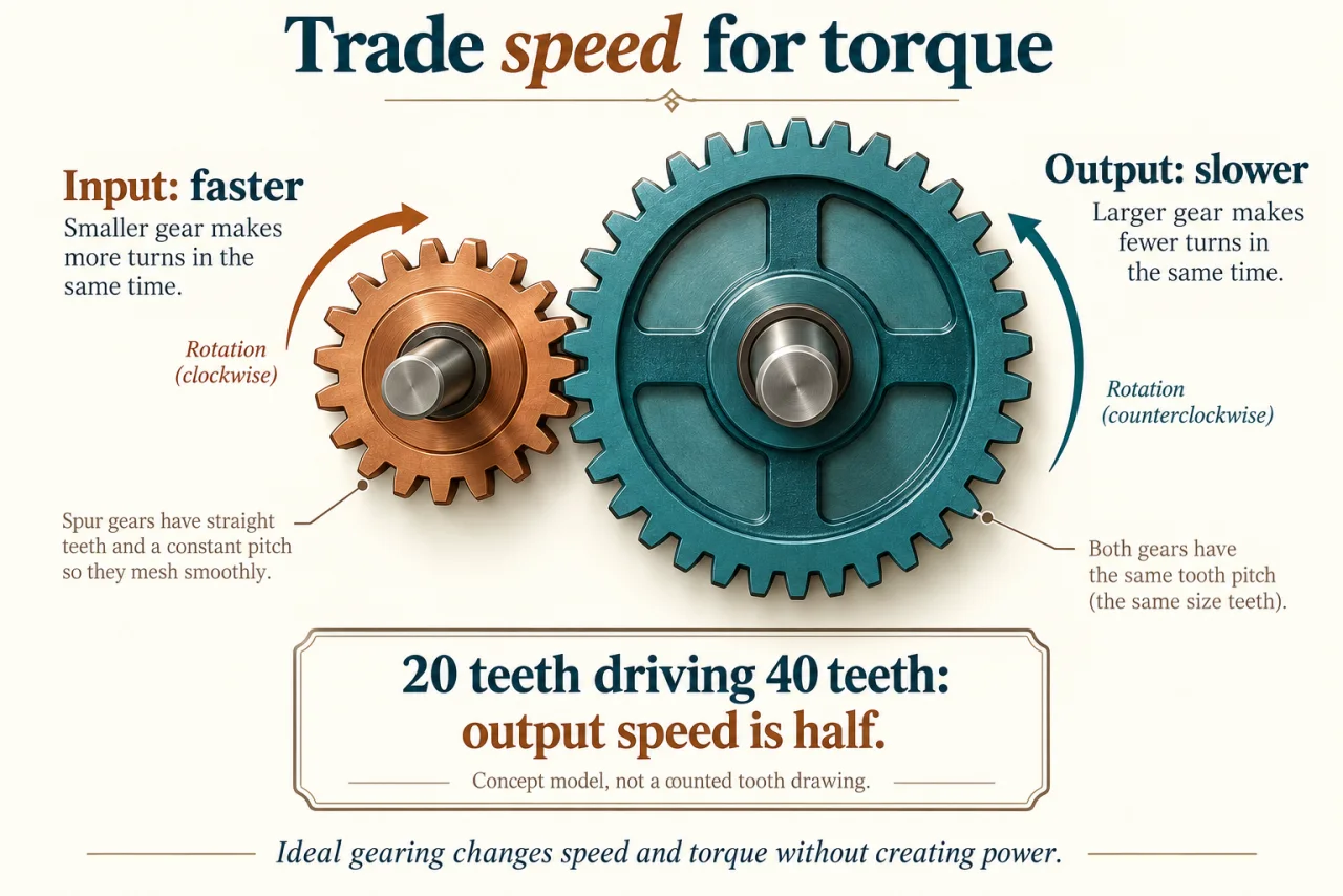
myAudience original rendered teaching illustration. Image: illustration, not a documentary photograph. · Operator-authored generated illustration; scientific concept model reviewed separately.
Gears exchange speed for torque
A pair of meshing gears transmits rotation by successive contact between teeth. The gears cannot choose independent speeds when they remain correctly engaged: tooth passage at the mesh must match. For two simple external spur gears, the shafts turn in opposite directions. This is a geometric constraint, not an extra energy source. Other arrangements, including internal gears and planetary sets, require different direction and ratio reasoning.
The illustration shows a small driving gear and a larger driven gear with opposite rotation arrows. The labels explain the intended 20-tooth/40-tooth calculation, but the artwork explicitly is not a counted-tooth engineering drawing. Use the given tooth counts for the numerical example rather than estimating a ratio from a decorative contour. Actual compatible gears require matching geometry, including module and appropriate tooth form, not just approximately similar-looking teeth.
Let the input gear have N₁ teeth and turn at n₁ revolutions per minute. It presents N₁n₁ teeth per minute at the mesh. The driven gear presents N₂n₂, so N₁n₁ = N₂n₂ and n₂ = n₁N₁/N₂. This derives the speed ratio rather than treating it as a fact to memorise. Tooth counts are discrete; a plausible decimal ratio does not justify rounding a manufactured gear’s tooth count arbitrarily.
For ideal lossless transmission, power in equals power out. Since rotational power is torque times angular speed, reducing output speed permits a corresponding increase in output torque. Doubling torque while halving speed keeps the product unchanged. Real bearings, tooth contact and lubricant behaviour introduce losses, so practical output power is smaller. A gearing choice cannot simultaneously double both speed and torque while keeping the same input power. For multiple stages, apply each stage’s efficiency to its input power. Efficiencies multiply rather than add. Combine the resulting total power fraction with the overall speed fraction to obtain torque amplification; that distinguishes a real transmission from a lossless kinematic sketch.
A useful extension is a multi-stage train. In a declared ideal two-stage arrangement, multiply the stage speed ratios, then handle direction separately by following each external mesh. An intermediate shaft may carry more than one fixed gear, making it different from a single idler. A simple idler can change direction and spacing without changing the magnitude of the overall end-to-end tooth-count ratio. State the arrangement before applying any formula. For a compound train, the gears rigidly fixed to one intermediate shaft share speed but not necessarily tooth count. For example, a 20-tooth driver can mesh with a 60-tooth gear whose shaft also carries a 15-tooth gear driving a 30-tooth output. The two ratios multiply to one sixth, while two external meshes return the output to the input rotation direction. Neither the compound arrangement nor its shaft supports are drawn in this single-pair plate.
Gear trains are established machine elements, but loads, wear, noise and alignment determine whether a particular design is suitable. KHK’s manufacturer reference is used for standard geometry and meshing relations, not to endorse a supplier. The mechanism plate and this ratio calculation do not specify a safe gearbox, tooth stress capacity or lubrication system. A durable transmission must satisfy those additional requirements as well as the desired motion.
Discuss: a manufacturer can make a cheap sealed transmission or a repairable design with replaceable wear parts. Compare initial cost, reliability, access to repair skills, material waste and lifetime affordability. Identify circumstances in which each choice could be defensible.
Image: illustration, not a documentary photograph.
Worked example: A compound two-stage external spur train has 20 teeth driving 60 teeth; the intermediate shaft also carries 15 teeth driving a 30-tooth output. Input is 240 rpm clockwise and 2 N·m. Stage efficiencies are 90% and 95%. Find output speed, direction, torque and total power loss.
First speed = 240 × 20/60 = 80 rpm, counterclockwise.
Second speed = 80 × 15/30 = 40 rpm, clockwise. Overall speed fraction = 1/6.
Total efficiency = 0.90 × 0.95 = 0.855. Torque amplification = 0.855 ÷ (1/6) = 5.13.
Output torque = 2 × 5.13 = 10.26 N·m.
Input angular speed = 240 × 2π/60 = 8π rad/s; input power = 16π ≈ 50.27 W.
Output power = 0.855 × 16π ≈ 42.98 W, leaving approximately 7.29 W transferred to other outputs such as heating.
Confirm output power independently: 10.26 × (40 × 2π/60) ≈ 42.98 W. Ratio arithmetic does not establish allowable tooth load.
Answer: 40 rpm clockwise, 10.26 N·m, approximately 42.98 W output and 7.29 W loss under the stated model.
Check your understanding: An engineer replaces the compound train with three separate gears: 20-tooth input, a freely rotating 60-tooth idler and a 30-tooth output. Will it still give one-sixth input speed? Justify the ratio and direction.
Answer: No. The idler factor cancels: (20/60) × (60/30) = 2/3. Two external meshes still give the same rotation direction as the input.
Why: A single idler uses the same tooth count in both meshes. The compound shaft instead carries separate 60- and 15-tooth gears; those are distinct kinematic arrangements.