Heat exchangers: recovering heat without mixing streams
By How things work · myAudience
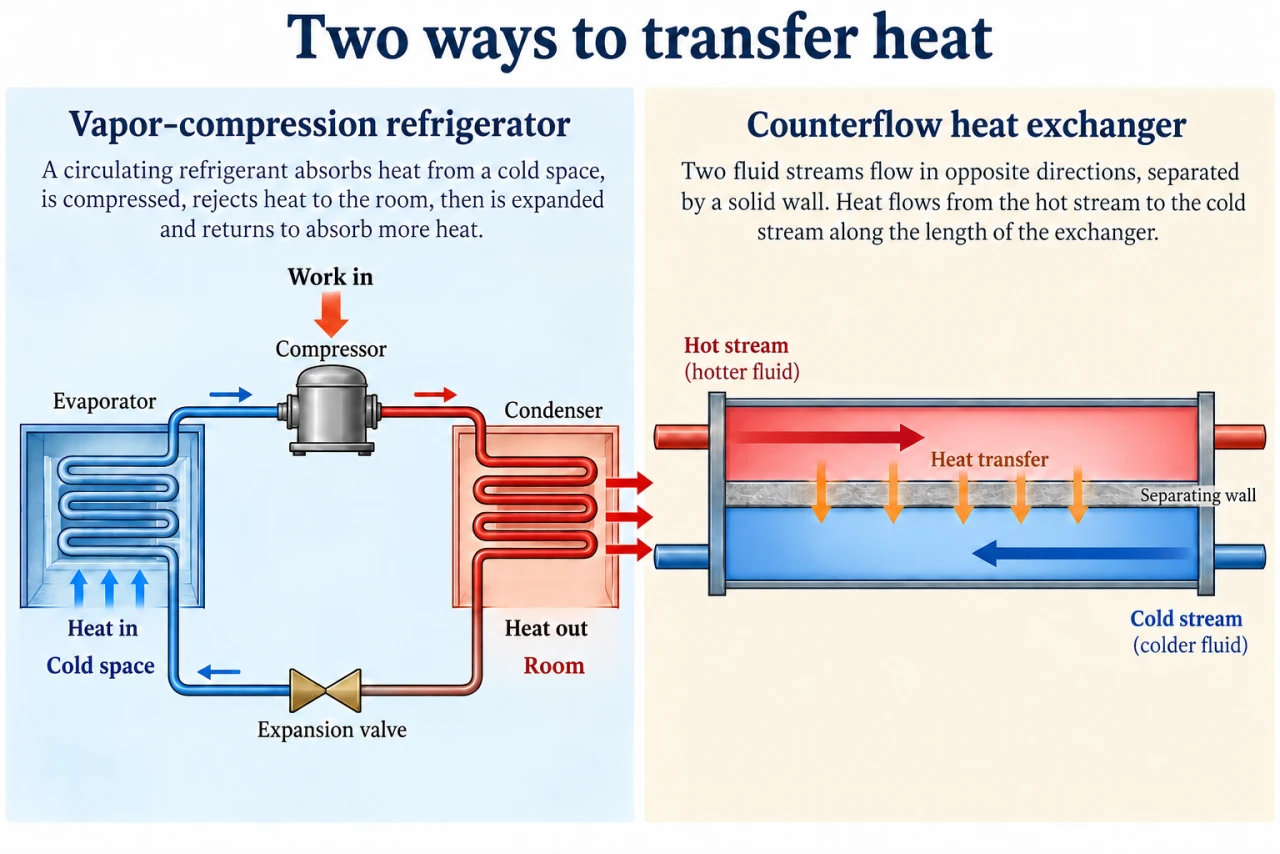
myAudience original imagegen teaching illustration; illustration, not a documentary photograph. · Original generated illustration; scientific and publication acceptance pending independent review.
Heat exchangers: recovering heat without mixing streams
The accepted heat-pump lesson moves energy using electrical work. Its evaporator and condenser are heat exchangers: energy crosses a wall between streams while each stream retains its own mass. Convection carries energy to and from the wall; conduction carries it through. Here we study a water-to-water sensible-heat exchanger, a distinct family, not a second heat-pump introduction.
A counterflow layout sends the streams in opposite directions. This can maintain a useful temperature difference along the exchanger. A cold outlet may be hotter than the hot outlet because those outlets lie at opposite ends; it must still be cooler than the hot inlet in this passive model. Co-current flow and counterflow have different terminal temperature constraints.
For steady flow with no phase change and constant specific heat, heat-capacity rate C = mass flow × cp has units W/K. Energy balance requires Qdot = Ch(Th,in − Th,out) = Cc(Tc,out − Tc,in) if heat lost outside is negligible. Equal heat rates do not imply equal temperature changes when C differs.
The maximum possible passive heat transfer for these inlet states is Qmax = Cmin(Th,in − Tc,in). Effectiveness ε = Qdot/Qmax describes approach to that limit, not work conversion efficiency. Fouling adds resistance; pumping incurs energy costs. A heat-pump system COP must include the chosen compressor, fan and pump boundary even if its exchanger has high effectiveness.
Use the right half of the shared plate: red hot fluid flows right and blue cold fluid flows left, with orange energy arrows crossing the separating wall. Each stream stays on its own side. Red and blue colours identify streams, not uniform temperatures along their lengths. The left refrigerator panel adds compressor work and must not be mistaken for a passive exchanger.
For discussion, heat recovery can reduce demand but also adds pumps, maintenance and possible contamination consequences if a wall fails. Who benefits from recovered heat, and who monitors faults? Evaluate useful recovered service against installation and upkeep burdens rather than effectiveness alone.
Image: illustration, not a documentary photograph.
Worked example: Counterflow water streams: Ch = 2000 W/K, Cc = 1000 W/K, hot inlet 60°C, cold inlet 20°C and ε = 0.60. Neglect external losses and phase changes. Find heat rate and outlet temperatures.
Cmin = 1000 W/K; Qmax = 1000 × 40 = 40,000 W. Qdot = 0.60 × 40,000 = 24,000 W.
Hot outlet = 60 − 24,000/2000 = 48°C. Cold outlet = 20 + 24,000/1000 = 44°C.
Terminal differences are 60 − 44 = 16 K and 48 − 20 = 28 K, both positive. Celsius differences equal kelvin differences here.
Answer: 24 kW transferred; hot outlet 48°C; cold outlet 44°C. No claim about area, pump input or actual product performance.
Check your understanding: 1: At the same rates/inlets, ε = 0.90 is proposed. Find both outlets. 2: The cold outlet exceeds the hot outlet: is conservation broken? Would the same pair be plausible for co-current flow?
Answer: Qdot = 36 kW; hot outlet 42°C and cold outlet 56°C. Counterflow terminal differences 4 K and 22 K remain positive. The two outlets are at different ends, so this is possible. In a passive co-current exchanger the outlet temperature difference could not reverse sign in this model.
Why: Credit requires checking energy balance on both streams and local terminal differences, rather than rejecting a temperature crossover by comparing different locations.