Bridges: trace forces before judging strength
By How things work · myAudience
myAudience original imagegen teaching illustration; illustration, not a documentary photograph. · Original generated illustration; scientific and publication acceptance pending independent review.
Bridges: trace forces before judging strength
A bridge transfers deck loads through structural members to supports and ground. In an ideal pin-jointed truss, members carry axial tension or compression; triangles constrain shape without relying on joint bending. In a suspension bridge, the main cable carries tension, towers mainly compression, and anchorages resist the cable pull. Real decks and joints add bending and other demands.
For the whole bridge in static planar equilibrium, vertical forces sum to zero and moments sum to zero. A simply supported beam has a pin and roller idealization: the roller permits longitudinal motion. This also explains why thermal expansion should not be confused with an applied vertical load.
Support reactions depend on where loads act. Replace a uniform self-weight by its resultant at the center only when taking whole-beam moments; this does not turn distributed bending into a single local force. Moment is force × perpendicular lever arm with units N m. Load sharing cannot generally be inferred from symmetry if the actual load is off-center.
Equilibrium is necessary but cannot prove capacity. Member stress, deflection, buckling, connections, fatigue, foundation settlement and wind or moving-load dynamics require further checks. Longer spans increase bending demand under many load models; making a member thicker is not a universal answer to stability or fatigue. The image shows a whole-beam free-body model, not member stresses or design dimensions.
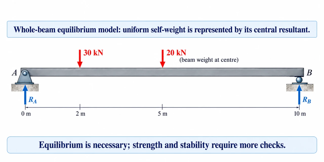
The beam plate places the 30 kN load at 2 m, the 20 kN whole-beam weight resultant at 5 m, and upward support reactions at A and B, 10 m apart. For the midspan cut, restore distributed self-weight on that segment; the drawn central resultant is valid for whole-beam moments, not a point load at every internal cut.
For discussion, bridge maintenance choices distribute access, cost and risk across communities and future users. What evidence should be public when repairs disrupt an essential route? Load equilibrium supplies only one necessary check; a budget argument cannot replace structural condition and capacity assessment.
Image: illustration, not a documentary photograph.
Worked example: Ideal 10 m simply supported beam. Uniform beam weight totals 20 kN; a 30 kN point load acts 2 m from A. Find vertical reactions, then verify with moments about B.
Whole beam: RA + RB = 50 kN. About A: RB × 10 = 20 × 5 + 30 × 2 = 160 kN m.
RB = 16 kN; RA = 34 kN.
Independent moment check about B: RA × 10 = 20 × 5 + 30 × 8 = 340 kN m, giving the same RA.
Answer: RA = 34 kN upward and RB = 16 kN upward. Ideal static reactions only; no structural safety conclusion.
Check your understanding: 1: Move the point load to x = 8 m. 2: At midspan, with the original load at x = 2 m, use the left segment to find bending-moment magnitude. Does correct equilibrium establish safe use?
Answer: Moved load reverses the reactions: RA = 16 kN, RB = 34 kN. Original midspan moment = 34 × 5 − 30 × 3 − (2 kN/m × 5 m) × 2.5 = 55 kN m. No: allowable stress, stiffness, stability and load combinations are not specified.
Why: Credit requires moment arms from the chosen cut or pivot, self-weight distribution on the cut segment, and a clear distinction between equilibrium and capacity.