Why a small crack matters in a ceramic
By How things work · myAudience
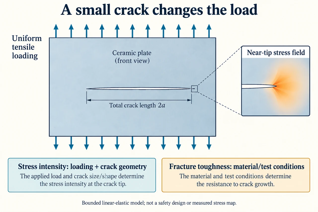
myAudience original rendered teaching illustration. Image: illustration, not a documentary photograph. · Operator-authored generated illustration; scientific model reviewed separately.
Why a small crack matters in a ceramic
A material can resist indentation yet be vulnerable to a sharp flaw under tension. Hardness, strength and fracture toughness are related to different tests and mechanisms; a hard surface is not a guarantee against crack growth. Brittle-material fracture concerns how a load and an existing flaw combine to concentrate deformation and stress near a crack tip. Ceramics are a varied material class, so neither a single toughness value nor a universal temperature capability describes every ceramic product.
The illustration shows a horizontal through-crack in a plate viewed from the front. The top arrows pull upward and the bottom arrows downward: the applied tension opens the crack, which is a mode-I loading situation. The dimension 2a spans the two tips; a is half that total length. The inset highlights one tip qualitatively. Its orange shading is not a measured stress field, and the finite rectangle does not establish the infinite-plate approximation used in the numerical exercise. The crack is drawn with visible width so readers can see it; actual crack-tip geometry and material response require separate evidence.
Within an appropriate linear-elastic fracture-mechanics model, stress intensity describes the loading and crack geometry, while fracture toughness characterises resistance under specified material and test conditions. Write Kᵢ = Yσ√(πa), where σ is remote tensile stress, a is crack half-length for the chosen central-crack definition, and Y is a geometry factor. Kᵢ has units of stress times square root of length, not simply stress. For a central crack in an effectively infinite plate Y = 1; another geometry cannot inherit that factor without justification. The sharp-tip mathematical model does not mean atoms withstand literally infinite physical stress.
The fictional example adopts fracture toughness Kᵢc = 2 MPa√m, σ = 100 MPa and Y = 1. These are teaching inputs, not a particular ceramic’s certified measurements. At the model’s threshold, a = [Kᵢc/(Yσ)]²/π, approximately 0.0001273 m. That is 127.3 micrometres for the half-length and 254.6 micrometres for the total crack. Using 127.3 micrometres as the total length would introduce a factor-of-two geometry error. Always identify the crack definition before inserting a size.
The model explains sensitivities rather than declaring an inspected part safe. At fixed toughness and geometry, quadrupling a doubles √a and therefore halves the threshold tensile stress. Improving the assumed toughness by 20% increases the threshold half-length by a factor of 1.2² = 1.44 at fixed stress and geometry. But changing the plate dimensions, crack shape, loading mode, temperature or environment can change the applicable relation or measured resistance. Cyclic loading, subcritical crack growth and non-linear material behaviour are outside this exercise.
Published toughness data must be read with their measurement methods, uncertainty, material preparation and conditions. The NIST compilation cited here is historical, with a 1998 data-update notice; it is not a current design specification or an endorsement of a supplier. Inspection, repair and replacement decisions require qualified assessment and appropriate current standards. More inspection and discarded material can carry costs, but treating uncertainty as someone else’s risk is not an ethical shortcut. This lesson asks learners to evaluate evidence and communicate model limits, not to test cracked household objects or certify structures.
Image: illustration, not a documentary photograph.
Worked example: For a fictional broad-plate central crack, use Y = 1, σ = 100 MPa and Kᵢc = 2 MPa√m. Find threshold half-length a and total length 2a. Then assess a = 50 micrometres within the same bounded model.
a = [2/(1 × 100)]²/π m = 0.00012732395… m ≈ 127.3 micrometres. Total length 2a ≈ 254.6 micrometres.
For a = 50 micrometres = 0.000050 m, Kᵢ = 100√(π × 0.000050) ≈ 1.253 MPa√m.
This computed intensity lies below the assumed 2 MPa√m threshold for this specified model. It does not evaluate fatigue, environmental growth, measurement uncertainty or service suitability.
Answer: Threshold a ≈ 127.3 micrometres and 2a ≈ 254.6 micrometres; at a = 50 micrometres the model gives Kᵢ ≈ 1.253 MPa√m, without establishing safety.
Check your understanding: A new model assumes 20% higher toughness at the same stress and geometry. How does threshold a change? Another report quadruples a but holds Kᵢc and Y fixed; what happens to threshold σ? Explain why an intact-looking thumbnail and an old table of typical values cannot validate either service claim.
Answer: The new toughness is 1.2 times the original, so threshold a becomes 1.44 times as large, about 183.3 micrometres; its total crack length is about 366.7 micrometres. Quadrupling a doubles √a, so threshold σ halves. A thumbnail cannot resolve or measure all relevant flaws, and a typical historical material value does not identify the actual part, preparation, conditions or uncertainty. Both calculations are conditional sensitivities, not verified performance conclusions.
Why: The square-root dependence and distinction between a and 2a determine the mathematical transfer. Evidence about an actual material, geometry and service environment is needed before using any simplified relation for a real decision.