Optical fiber: encoding light and preserving a signal
By How things work · myAudience
myAudience original imagegen teaching illustration; illustration, not a documentary photograph. · Original generated illustration; scientific and publication acceptance pending independent review.
Optical fiber: encoding light and preserving a signal
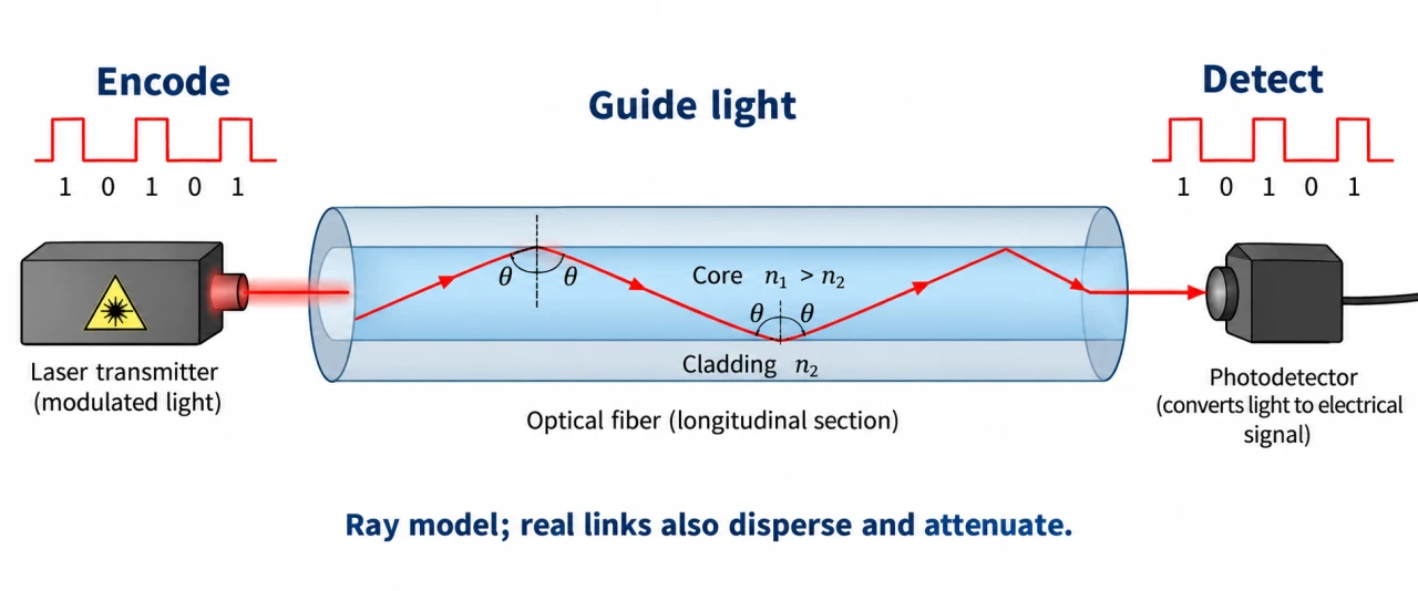
A transmitter converts an electrical symbol stream into a changing optical signal. A fiber guides that light; a detector converts arriving optical energy back to an electrical signal for decoding. The fiber does not know the meaning of a message. Encoding, propagation and detection are separate jobs, and a surviving pulse need not preserve every timing detail.
In a simple ray model, core refractive index exceeds cladding index. Incidence above the critical angle, measured from the normal inside the core, gives total internal reflection. The guided-wave description is needed for real single-mode fiber. A reflection sketch is a useful geometric model, not proof that a real fiber has no losses.
Attenuation reduces power; dispersion spreads pulses in time and can make neighboring symbols harder to distinguish. Neither is simply propagation delay. For a uniform index model, speed v = c/n and travel time t = nL/c. A link can have high symbol rate while each message still takes milliseconds to travel.
Define power loss in decibels as 10 log10(Pin/Pout); losses from successive sections add in dB because transmitted power fractions multiply. A receiver sensitivity threshold is only one part of a link budget. Connector loss, margins, dispersion and detector noise are excluded from the toy model and must be added before a performance claim.
The plate encodes 1–0–1–0–1 at the source and detects the same illustrative sequence at the receiver. Ray angles are measured from dotted interface normals, with core index greater than cladding. This shows a bounded ray model, not exact single-mode fields or zero attenuation. Pulse heights and reflected path lengths are conceptual, not the worked link budget.
For discussion, a fast optical backbone can coexist with unaffordable household access or poor repair coverage. Compare reliability, excavation impact, repairability and equitable last-mile service. A low optical loss alone does not demonstrate that people can meaningfully connect.
Image: illustration, not a documentary photograph.
Worked example: Invented fiber: L = 20 km, n = 1.50, c = 3.00 × 10⁸ m/s. Attenuation 0.20 dB/km, launch power 1.0 mW, no other losses. Find delay and received power.
L = 20,000 m. t = 1.50 × 20,000/(3.00 × 10⁸) = 0.000100 s = 100 µs.
Loss = 0.20 × 20 = 4 dB. Pout = 1.0 × 10^(−4/10) = 0.3981 mW.
Delay is a transit time, not the inverse data rate; simultaneous pulses can be in flight.
Answer: 100 µs one-way propagation and 0.3981 mW received under the declared ray/attenuation model.
Check your understanding: 1: Double length and add a 2 dB connector loss; calculate power and delay. 2: Why does doubling launch power not remove dispersion?
Answer: Fiber loss 8 dB plus connector 2 dB = 10 dB: received power 0.100 mW; fiber delay 200 µs, neglecting connector delay. More power may help amplitude detection but does not reverse differential pulse travel times; it cannot by itself restore a broadened waveform.
Why: Credit requires additive dB losses, exponential power conversion, independent time calculation and distinction between amplitude, waveform shape and throughput.