Printing a shape is not the same as making a sound part
By How things work · myAudience
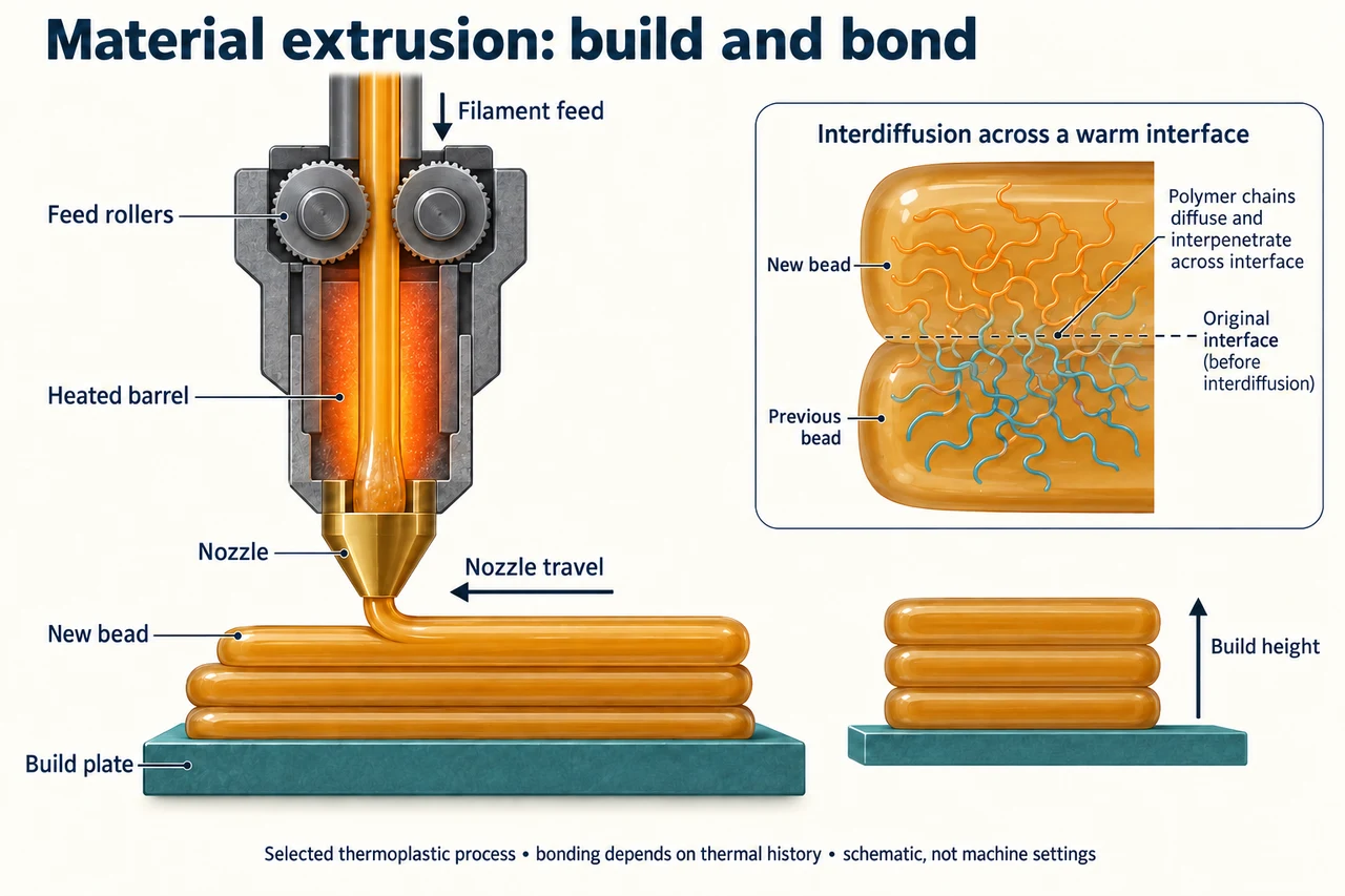
myAudience original rendered teaching illustration. Image: illustration, not a documentary photograph. · Operator-authored generated illustration; scientific model reviewed separately.
Printing a shape is not the same as making a sound part
This lesson selects thermoplastic material extrusion, one additive manufacturing route. A heated feed passes through a nozzle; controlled relative movement places beads on a build surface, then further layers add height. Other printing methods use different feedstocks and joining processes. A visible shape is evidence that material was placed, not evidence that a particular strength, dimensional tolerance or lifetime requirement has been met. The digital model, deposited material and tested finished part are three different things.
The plate follows filament downward through the heated barrel and nozzle to a new bead above earlier material. Its short leftward arrow identifies nozzle travel, with deposited material trailing to the right rather than appearing ahead of the nozzle; it is not a flow arrow through a solid wall. The enlarged interface shows molecular interpenetration as a qualitative idea, not newly created chemical crosslinks. Adjacent curves are not measured chain counts. NIST’s material-extrusion overview identifies layer construction, while its 2017 research abstract relates interlayer welding to polymer interdiffusion during changing thermal conditions. No experimental strength value or optimal machine setting is inferred from that abstract.
A slicing representation divides the intended build height into layers and plans deposition. In an idealised uniform-height model,20 mm at 0.20 mm per layer needs 100 layers; at 0.10 mm it needs 200. This doubles the layer count, not automatically the deposited volume, strength, time or electricity. A solid cuboid retains its geometry when divided more finely. Real walls, infill, supports, gaps and machine movements need their own accounting. A finer layer can change several conditions at once, so a useful comparison identifies which were held constant.
Use a separate original material budget. Suppose a fictional finished part contains 30 cm³ of polymer, removable supports use 6 cm³ and purge consumes 4 cm³. With no other loss or void volume counted, the feed volume is 40 cm³, or 40,000 mm³. A uniform 1.75 mm diameter filament has circular area π ×1.75²/4 ≈2.4053 mm². Length is volume divided by area, giving about 16,630 mm or 16.630 m. Calling 30 cm³ the purchased material ignores 10 cm³ that does not remain in the useful part. The model assumes constant diameter and conservation of polymer volume; it does not specify melt pressure or real shrinkage.
Now compare a second route that retains the same 30 cm³ part but uses 2 cm³ of support and 8 cm³ of purge. Total feed remains 40 cm³, so the same filament length is required in this model. Lower support waste alone has not improved total material efficiency: part-volume/feed-volume is 30/40 =75% for both. A claim of better environmental performance still needs evidence about electricity, rejected parts, service life, feed production and collection. The example demonstrates how moving a loss outside the headline category can disguise an unchanged total.
Compare proposals against an actual purpose rather than a fashionable process name. A prototype for fit, a decorative object and a loaded component need different evidence. Layer relationships can affect properties, but the drawing cannot qualify a printed medical device, load-bearing part or food-contact item. Supports removed, a clean surface and a detailed digital file are not substitutes for appropriate inspection and testing. Responsible access also includes who can afford equipment, who encounters emissions and waste, and whether a useful repair avoids replacing a larger assembly. No universal recycling or sustainability benefit follows from the word additive.
Image: illustration, not a documentary photograph.
Worked example: A fictional part retains 30 cm³ polymer. Supports require 6 cm³ and purge 4 cm³. Assume all feed is uniform circular filament of diameter 1.75 mm, no uncounted loss, and conserved polymer volume. Find required feed length and retained material fraction.
Total volume =30 +6 +4 =40 cm³ =40,000 mm³.
Filament area =π ×1.75²/4 ≈2.4053 mm². Length =40,000/2.4053 ≈16,630 mm =16.630 m.
Retained fraction =30/40 =0.75 =75%. The discarded support/purge fraction is 25%, not 10/30.
Answer: Approximately 16.630 m of filament;75% of the counted feed volume remains in the part.
Check your understanding: Another route uses 2 cm³ supports and 8 cm³ purge for the same 30 cm³ part. Is its retained-material efficiency better? If actual filament diameter is 1.70 rather than 1.75 mm, what changes for the same 40 cm³ feed volume? Does halving layer height prove twice the strength?
Answer: Support waste is lower, but total is still 40 cm³ and retained efficiency 75%. Area at 1.70 mm isπ ×1.70²/4 ≈2.2698 mm², so length is about 17.623 m, about 5.969% longer than 16.630 m. The cross-sectional area depends on diameter squared; a diameter change is not a proportional length change. Halving layer height doubles idealised layer count for fixed height, but no strength result follows without appropriate evidence.
Why: Track all material losses inside the same boundary. Keep volume/length/diameter units consistent and distinguish geometric subdivision from measured mechanical performance.