A cutter follows a reference, not the outline on a screen
By How things work · myAudience
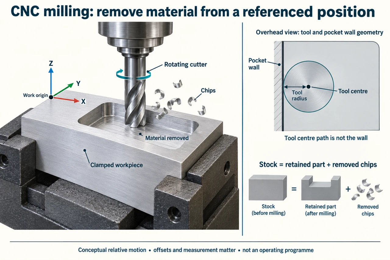
myAudience original rendered teaching illustration. Image: illustration, not a documentary photograph. · Operator-authored generated illustration; scientific model reviewed separately.
A cutter follows a reference, not the outline on a screen
CNC milling is a selected subtractive manufacturing process. A rotating cutting tool removes material from clamped stock through controlled relative motion. The final surface depends on the tool’s geometry and position relative to the workpiece, not simply the outline of an image or a model file. This lesson explains reference frames and accounting; it supplies no machine programme, cutting speed, feed setting or permission to operate equipment.
The plate separates the cutter, clamped workpiece and removed chips. Its work-origin dot and three axes establish a local reference; they are not a measured setup. The small overhead inset keeps the tool-centre dot one radius inside the intended straight pocket wall. The edge of the cutter reaches that wall while its centre does not. Tool radius, length, fixture clearances and changing work references therefore matter when interpreting a path. A drawing cannot confirm that a real cutter or workholding system clears every obstacle.
Autodesk’s coordinate explanation distinguishes machine coordinates from a work coordinate system and describes offsets between them. It also explains motion from the tool’s position relative to the part: a table moving one way can create relative tool motion the other way. Our conventional local frame does not establish every machine’s axis arrangement or startup procedure. A correct numeric coordinate in the wrong reference frame can still produce the wrong geometry. The reference must be connected to the physical stock and verified appropriately, not silently assumed from a rendered model.
Consider a fictional stock block 100 mm ×60 mm ×20 mm. Its volume is 120,000 mm³ =120 cm³. An idealised rectangular-envelope pocket 50 mm ×30 mm ×5 mm represents 7,500 mm³ =7.5 cm³ of removal. At assumed constant density 2.7 g/cm³, stock mass is 324 g, removed mass 20.25 g and retained mass 303.75 g. These are mass-conservation quantities, not a manufacturing plan. A real round cutter leaves rounded internal corners unless another process changes them; our rectangular-envelope volume deliberately ignores those corner corrections and must not be presented as an exact machined-pocket mass.
Inspect that geometric limit rather than hiding it. If the same pocket’s plan has four internally rounded corners of radius 5 mm, the area retained at its corners relative to a sharp rectangle is 4 ×(5² −π ×5²/4) =25 ×(4 −π) ≈21.460 mm². At uniform depth 5 mm this means about 107.301 mm³ less removal. Removed volume becomes 7,392.699 mm³, or 7.392699 cm³; at the chosen density removed mass is 19.960287 g and retained mass 304.039713 g. This ideal rounded-rectangle model still ignores tool wear, runout, surface texture and measurement uncertainty.
Suppose a designer asks a radius 5 mm tool to make a sharp internal corner and says moving its centre onto the intended wall solves the problem. That confuses the tool centre with the swept cutting envelope: at a straight wall, putting the centre on the wall cuts beyond it by the radius. Nor can a circle fit into an arbitrarily sharp internal corner while preserving both walls. A suitable geometry or different verified process is needed. Precision also involves measurement and fixturing evidence. Chips may have recovery value, but collection, mixed materials, coolant, power, rejects and finished service life all affect a fair lifecycle comparison; subtractive does not mean that every removed gram becomes usable new stock.
Image: illustration, not a documentary photograph.
Worked example: A fictional 100 ×60 ×20 mm block of uniform density 2.7 g/cm³ has a 50 ×30 ×5 mm sharp-rectangle pocket envelope. Compute initial, removed and retained masses. This is an envelope estimate, not an exact round-cutter result.
Stock =120,000 mm³ =120 cm³; mass =120 ×2.7 =324 g.
Pocket envelope =7,500 mm³ =7.5 cm³; removed mass =7.5 ×2.7 =20.25 g.
Retained mass =324 −20.25 =303.75 g. Removed/initial mass =20.25/324 =6.25%.
Answer: 324 g initial,20.25 g removed and 303.75 g retained in the sharp-rectangle envelope model.
Check your understanding: Replace the pocket plan with a rounded rectangle having four radius 5 mm corners at depth 5 mm. Calculate corrected removal and explain why a 5 mm radius tool centre cannot simply follow the wall. Would changing the work-coordinate origin alter the intended physical shape?
Answer: Each rounded corner retains r² −πr²/4 relative to the sharp rectangle. Four corners retain 25(4 −π) ≈21.460 mm² of plan area, or 107.301 mm³ at depth 5 mm. Removal is 7,500 −107.301 =7,392.699 mm³; mass 19.960287 g, leaving 304.039713 g. At a straight wall the centre must remain one radius inside the pocket for its edge to reach the wall; centre-on-wall would cut beyond it. Relocating a reference origin should not change intended physical geometry if all coordinates and offsets are transformed consistently. Changing only the origin without consistent transformation can misplace it.
Why: Transfer tests the difference between a simplified envelope and a tool-compatible geometric model, unit conversion, mass balance and reference-frame invariance. Neither computation replaces machining or inspection evidence.