Distribution protection: sensing is not interruption
By How things work · myAudience
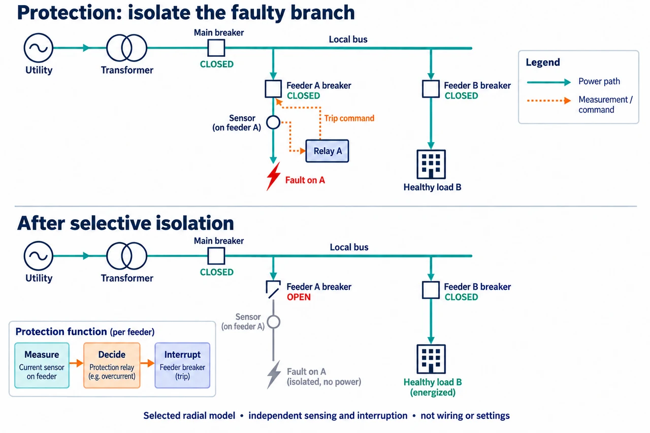
myAudience original rendered teaching illustration. Image: illustration, not a documentary photograph. · Operator-authored generated illustration; scientific model reviewed separately.
Distribution protection: sensing is not interruption
A distribution substation transfers electricity into a local network while equipment monitors and protects selected parts. A transformer changes voltage through magnetic coupling, but does not itself identify every faulty downstream branch. Protection has a separate purpose: detect an abnormal condition and interrupt the appropriate path before unacceptable damage or exposure. This lesson follows a selected radial network with one source and two branches. Networks with multiple sources or different grounding and fault conditions need additional analysis.
Read the upper plate as functional relationships. The utility supplies a transformer and closed main breaker, then a bus divides into feeders A and B. A current sensor measures A; the relay receives a measurement and can send a trip command to A’s breaker. The orange dotted route carries information, not feeder load power through the relay. The breaker supplies the interrupting action. In the lower selected outcome A’s contact gap is open, while the main path and B remain connected. That is selective isolation, not proof every fault is detectable by a single current threshold.
Why separate these functions? A relay can correctly decide to trip while the breaker fails to open; conversely a healthy breaker cannot compensate for an unsuitable measurement or decision. Instrument transformers scale current or voltage for measurement, and real sensing can introduce error, including current-transformer saturation. Reliable control power and a functioning command/actuation chain matter during disturbances. The Schneider primary explanation treats these as parts of a protection system. A fault current must not be inferred from ordinary demand alone: source impedance, network topology and the kind and location of fault alter it.
An original idealised sensing example uses a stipulated 200:1 current ratio with no error. A primary current of 600 A corresponds to 3 A secondary; 1,000 A corresponds to 5 A. Multiplying or dividing by the wrong ratio changes the inferred primary current by orders of magnitude. This example only establishes scaling under its assumptions. It does not select a current transformer, specify permissible secondary handling, calculate saturation or recommend a relay threshold. Three-phase, earth-fault and directional measurements require their own defined quantities and evidence.
Coordination also requires time and uncertainty, not merely different labels on breakers. In a fictional timing account, A’s relay decision takes 0.08 s and A’s breaker then needs at most 0.05 s, giving 0.13 s to interrupt after the stated starting event. An upstream backup decision occurs at 0.25 s, leaving 0.12 s between successful downstream clearing and backup decision in this simplified model. If downstream breaker time becomes 0.20 s, clearing would take 0.28 s, so that claimed order fails. Real coordination uses complete time–current behaviour, device tolerances, measurement uncertainty and fault ranges; these numbers are not equipment settings or adequate design margins.
Protection preserves some service by deliberately removing other service, so assess both safety and continuity. In a selected normal-load account, A serves 40 kW and B serves 60 kW. Successful isolation of A leaves 60 kW served; loss of the upstream path removes both, totalling 100 kW before considering any alternative supply. These are ordinary demand quantities, not fault-current or fault-energy estimates. Operators need transparent essential-service priorities and maintenance evidence; vulnerable people may be harmed by outages even when equipment is protected. Neither reduced outage scope nor a functioning diagram proves safe access to de-energised equipment.
Image: illustration, not a documentary photograph. Functional relationships are conceptual, not physical wiring or equipment operating instructions.
Worked example: Under the original ideal sensor ratio 200:1, infer primary current from 2.5 A secondary. A relay decides after 0.10 s and the breaker clears 0.06 s later; an upstream backup decides at 0.30 s. Calculate scaling and simplified time gap.
Primary current = 2.5 × 200 = 500 A under the ideal ratio.
Downstream clearing = 0.10 + 0.06 = 0.16 s. Gap before upstream decision = 0.30 − 0.16 = 0.14 s.
This is an original arithmetic account, not a qualified coordination result; full characteristics, tolerances and fault scenarios are omitted.
Answer: 500 A ideal primary current and 0.14 s simplified gap; no actual settings or protection adequacy established.
Check your understanding: For the main timing model, the breaker now needs 0.20 s after the 0.08 s decision. Compare clearing with the 0.25 s backup decision. If the breaker never clears, does a correct relay decision alone isolate A? Can the 40 kW A demand establish fault current?
Answer: Clearing would occur at 0.28 s, later than the 0.25 s backup decision by 0.03 s. The claimed downstream-first ordering no longer holds. A correct command alone does not interrupt the path if the breaker fails; suitable backup may isolate a larger region. Normal 40 kW demand does not determine fault current, which needs network/fault impedance and topology information.
Why: Apply units, declared boundaries and assumptions; distinguish a necessary calculation from evidence of real performance or safe design.