Solar inverter: a waveform is not a new energy source
By How things work · myAudience
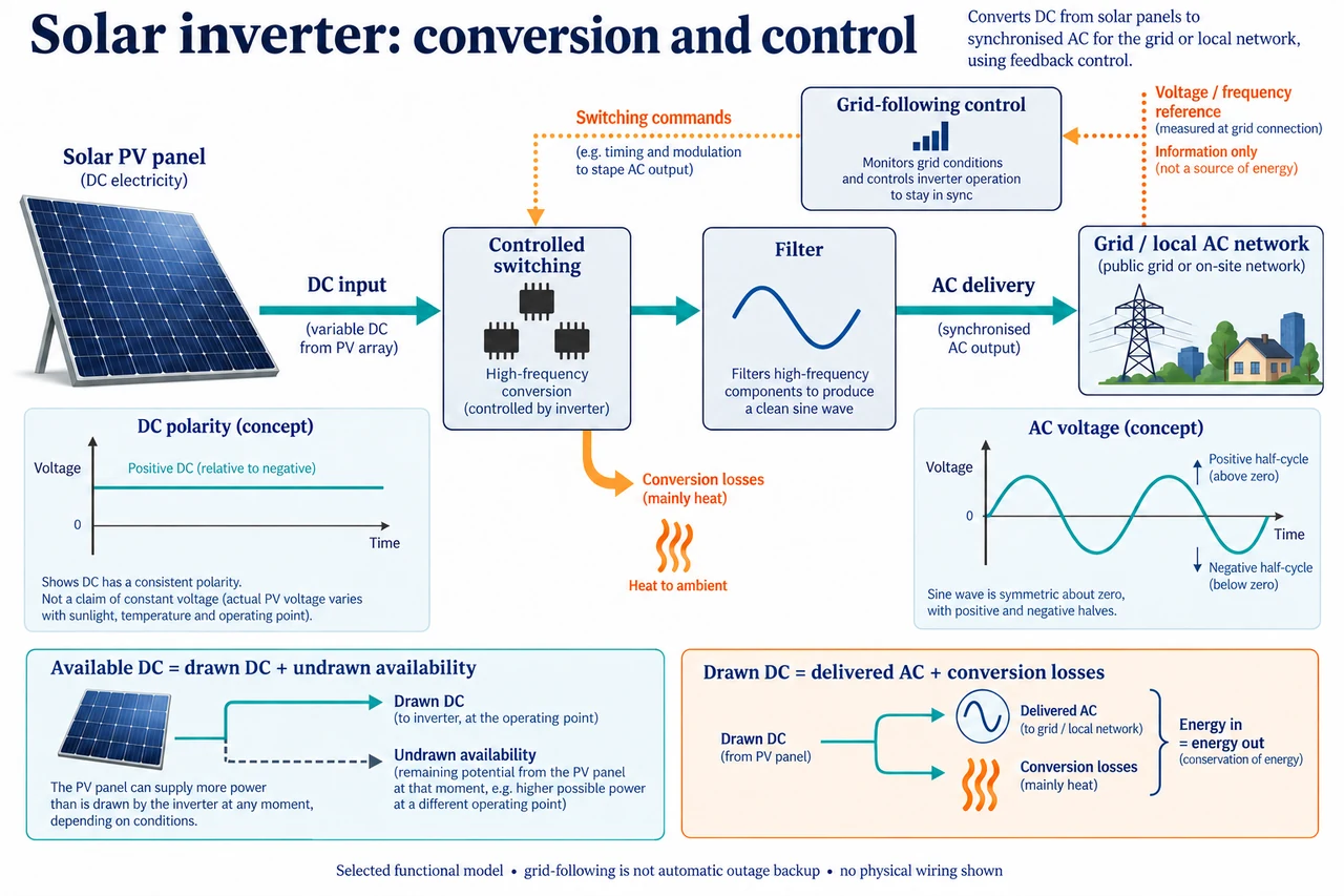
myAudience original rendered teaching illustration. Image: illustration, not a documentary photograph. · Operator-authored generated illustration; scientific model reviewed separately.
Solar inverter: a waveform is not a new energy source
A solar photovoltaic module supplies DC electrical output whose voltage and current depend on operating conditions. The inverter uses controlled power-electronic switching to deliver suitable AC at another boundary. It changes the form of electrical supply; it does not create additional energy from switching. A DC supply is not necessarily constant in magnitude merely because its polarity is described as direct current. The selected plate separates solar DC, controlled switching and filtering, then AC delivery and a grid-reference signal.
Follow the functional blocks rather than treating the plate as a circuit to construct. Solar DC enters a switching stage, followed by filtering and controlled AC delivery to the grid or local network. The schematic traces distinguish input polarity from an output that alternates. Actual modulation, semiconductor arrangement, filtering and protection vary. A grid-following controller uses an existing voltage/frequency reference; a suitably designed grid-forming system can establish a reference. A panel plus any arbitrary inverter therefore does not guarantee backup electricity during a grid outage. The DOE overview makes operation without grid support conditional on suitable design.
Use an original fixed-efficiency account to quantify conversion. If available DC input is 5.0 kW and selected conversion efficiency is 96%, AC real output before any other stated limit would be 4.8 kW, with 0.2 kW transferred to conversion losses. If the inverter has an independent 4.0 kW real-output limit, that AC output cannot simply become 4.8 kW. Under a simplified constant 96% model, producing 4.0 kW requires 4/0.96 =25/6 kW DC, about 4.1667 kW. The remaining 5 −25/6 =5/6 kW of available input is curtailed or otherwise not drawn at this selected boundary; it is not automatically all heat inside the inverter.
Energy integration exposes why one midday power number is insufficient. Suppose the first fictional hour has 2.0 kW available DC and the next hour 5.0 kW, with the same 96% efficiency and 4.0 kW output cap. First-hour AC delivery is 1.92 kWh; second-hour delivery is 4.0 kWh, totalling 5.92 kWh. Available DC energy is 7.0 kWh. Actual drawn DC energy is 2 +25/6 =37/6 kWh; conversion loss is 37/6 −5.92 =37/150 kWh, about 0.2467 kWh. Undrawn availability is 5/6 kWh. Thus 7.0 =5.92 +37/150 +5/6, under the declared model. Calling every shortfall conversion loss would hide curtailment.
Real and apparent power are different capacities. For sinusoidal voltage and current with phase difference φ, define S = Vrms Irms, P = S cos φ and Q = S sin φ. The identity cos² φ + sin² φ = 1 gives S² = P² + Q²; signs depend on the chosen power-flow convention, so this example uses magnitudes. For a stipulated sinusoidal single-phase example with 230 V RMS and 10 A RMS, apparent power is 2.3 kVA. At power factor 0.80, real power is 1.84 kW; the magnitude of reactive power is sqrt(2.3² −1.84²) =1.38 kvar under the sinusoidal assumption. A 2.3 kVA capability does not imply that 2.3 kW real output can be delivered simultaneously with 1.38 kvar. With that same apparent-power ceiling and reactive-power magnitude, real-power magnitude is at most 1.84 kW. This model is not a particular inverter rating, harmonics calculation or utility requirement; real capability maps depend on equipment and conditions.
The distinction matters for responsible claims about solar usefulness. Waveform control can support grid operation, but power and energy must come from available generation or storage and stay within equipment capabilities. Conversion efficiency, clipping, shading, downtime, local connection limits and repairability affect useful delivery. Microinverters and string architectures offer different trade-offs, not universal winners. Remote monitoring also creates communication and security responsibilities. Communities deserve clear information about export constraints, backup capabilities, maintenance and who bears network upgrade costs, rather than a promise that nameplate panel power is continuously available AC service.
Image: illustration, not a documentary photograph. Functional relationships are conceptual, not physical wiring or equipment operating instructions.
Worked example: Use an original constant-efficiency model:4.0 kW available DC,90% conversion efficiency and 3.0 kW AC output cap for 2 h. Find delivered energy, drawn DC energy, conversion loss and undrawn availability.
Without cap, real AC output would be 3.6 kW; the 3.0 kW cap binds. Drawn DC power =3/0.90 =10/3 kW.
Over 2 h, delivered AC energy =6 kWh; drawn DC =20/3 kWh; conversion loss =2/3 kWh.
Available DC energy is 8 kWh; undrawn availability =8 −20/3 =4/3 kWh. Balance:8 =6 +2/3 +4/3.
Answer: 6 kWh delivered;2/3 kWh conversion loss and 4/3 kWh undrawn availability, under fictional boundaries.
Check your understanding: In the main two-hour example, a colleague calls 7 −5.92 =1.08 kWh inverter heat loss. Explain the error. For a sinusoidal 2.3 kVA limit with 1.38 kvar magnitude, find maximum real power and explain why panel DC power cannot prove outage backup.
Answer: The 1.08 kWh shortfall combines 37/150 kWh actual conversion loss with 5/6 kWh undrawn availability; they are different destinations. The sinusoidal capability relation gives sqrt(2.3² −1.38²) =1.84 kW real magnitude, not 2.3 kW plus reactive duty. Backup requires an appropriately engineered reference, protection, isolation and adequate sources/storage; a DC panel output number establishes none of those.
Why: Apply units, declared boundaries and assumptions; distinguish a necessary calculation from evidence of real performance or safe design.