UPS: power continuity is an energy and capacity problem
By How things work · myAudience
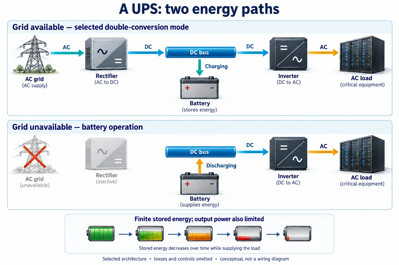
myAudience original rendered teaching illustration. Image: illustration, not a documentary photograph. · Operator-authored generated illustration; scientific model reviewed separately.
UPS: power continuity is an energy and capacity problem
A UPS bridges a loss of incoming supply using stored energy and power-conversion equipment. It does not make energy, replace every outage-protection measure or guarantee that every connected appliance can run. The selected double-conversion architecture converts incoming AC to a DC bus, then an inverter converts bus power back to AC for the load. Other UPS architectures and operating modes exist. In this lesson, backup means a bounded interval for continuity or orderly shutdown, not unlimited operation.
Read the upper picture from left to right: AC grid, rectifier, DC bus, inverter, AC load. The downward branch represents battery charging while input is available. In the lower picture, the grey input equipment has no flow arrows: the battery supplies the DC bus, which still supplies the inverter and AC load. The inverter does not obtain AC directly from the battery; conversion remains necessary. The arrows describe energy routes, not conventional-current polarity, actual protective devices or relative power. Bypass modes and detailed charge controls are omitted rather than claimed absent in real installations.
Separate energy capacity from output-power capability. Suppose a fictional battery contains 2.0 kWh on the stated stored-energy basis, only 80% is permitted to be withdrawn, and the inverter delivers 90% of withdrawn energy to the AC load. Usable AC energy is 2.0 × 0.80 × 0.90 = 1.44 kWh. For a constant 0.60 kW AC load, time is 1.44/0.60 = 2.4 h. The units expose the reasoning: kWh divided by kW gives hours. This model assumes the stated energy fraction and efficiency remain constant and auxiliary demand is absent; real temperature, ageing, discharge rate and cut-off behaviour can change runtime.
A sufficiently large energy store can still fail to supply a large load. If the fictional inverter is limited to 1.0 kW real output, a 1.20 kW demand exceeds that model limit even though the battery contains energy. Reducing demand to 0.60 kW resolves this particular real-power inequality, not every electrical constraint. Real equipment also has apparent-power, power-factor, surge and thermal ratings. Do not equate a kVA label to kW without the relevant conditions. A motor starting transient or overload can matter before the energy store is substantially depleted.
Account for normal-mode losses too. In an original steady model, the AC load needs 0.60 kW and the battery is simultaneously absorbing 0.20 kW of DC charging power. With inverter efficiency 0.90, the load branch draws 0.60/0.90 = 2/3 kW from the bus. The rectifier supplies 2/3 + 0.20 = 13/15 kW DC. At rectifier efficiency 0.95, input is (13/15)/0.95 = 52/57 kW, about 0.9123 kW. Inverter loss is 1/15 kW; rectifier loss is 13/285 kW. Input equals delivered load plus DC charging plus these losses. Charging power here is at the battery boundary; further battery charging losses are outside this selected account.
Planning continuity requires a time-varying budget and a fair definition of essential service. If the fictional 1.44 kWh AC allowance serves 0.60 kW for 0.50 h, it uses 0.30 kWh, leaving 1.14 kWh. A subsequent constant 0.30 kW load can run for another 3.8 h, for 4.3 h total under this model. Prioritising medical communication over a decorative display may be defensible, but priorities need transparent rules and consideration of disabled users and people without alternative services. Purchase price or runtime alone does not establish lifecycle benefit: battery materials, replacement, safe recovery and conversion losses belong in the comparison.
Image: illustration, not a documentary photograph. The plate is a functional concept model, not physical wiring, switching instructions or a performance guarantee.
Worked example: Use an original model with 3.0 kWh stored energy, a 70% withdrawable fraction, 85% conversion efficiency and constant 0.50 kW AC demand. Find runtime and explain why a separate 0.40 kW inverter rating changes the feasibility conclusion.
Usable AC energy is 3.0 × 0.70 × 0.85 = 1.785 kWh. Energy-only runtime is 1.785/0.50 = 3.57 h. But 0.50 kW exceeds the stated 0.40 kW real-output limit: the demanded service is infeasible in this rating model, so 3.57 h is not a permissible operating claim.
Answer: Usable AC energy is 3.0 × 0.70 × 0.85 = 1.785 kWh. Energy-only runtime is 1.785/0.50 = 3.57 h. But 0.50 kW exceeds the stated 0.40 kW real-output limit: the demanded service is infeasible in this rating model, so 3.57 h is not a permissible operating claim.
Check your understanding: In the main 1.44 kWh AC-energy model, serve 0.80 kW for 0.25 h and then 0.40 kW. Calculate total duration. A colleague adds 1.44/0.80 and 1.44/0.40; explain the error. State one reason real runtime can differ.
Answer: The first interval uses 0.80 × 0.25 = 0.20 kWh. Remaining energy is 1.24 kWh, giving 1.24/0.40 = 3.10 h afterward, or 3.35 h total. Adding two full-store runtimes spends the same initial energy twice. Ageing, temperature, changing efficiency or discharge/cut-off behaviour can invalidate the constant usable-energy assumptions; output and surge limits must also be checked.
Why: Apply declared energy boundaries, units and separate power constraints; original fictional models do not certify installation operation.