Stored bits need a physical state that survives power loss
By How things work · myAudience
myAudience original rendered teaching illustration. Image: illustration, not a documentary photograph. · Operator-authored generated illustration; scientific model reviewed separately.
Stored bits need a physical state that survives power loss
Nonvolatile storage retains a physical state after its power supply is removed. That is different from continuously maintaining a value in working memory, and different again from guaranteeing a permanent archive. NAND flash and magnetic recording provide two useful contrasting examples. They still require power and functioning electronics to write, find and read data. A device can therefore retain a recorded state while its controller, interface or surrounding system is unable to retrieve a file. This lesson explains selected mechanisms and deliberately fictional capacity-normalised calculations; it does not predict a particular drive’s service life, data retention, recovery success or security.
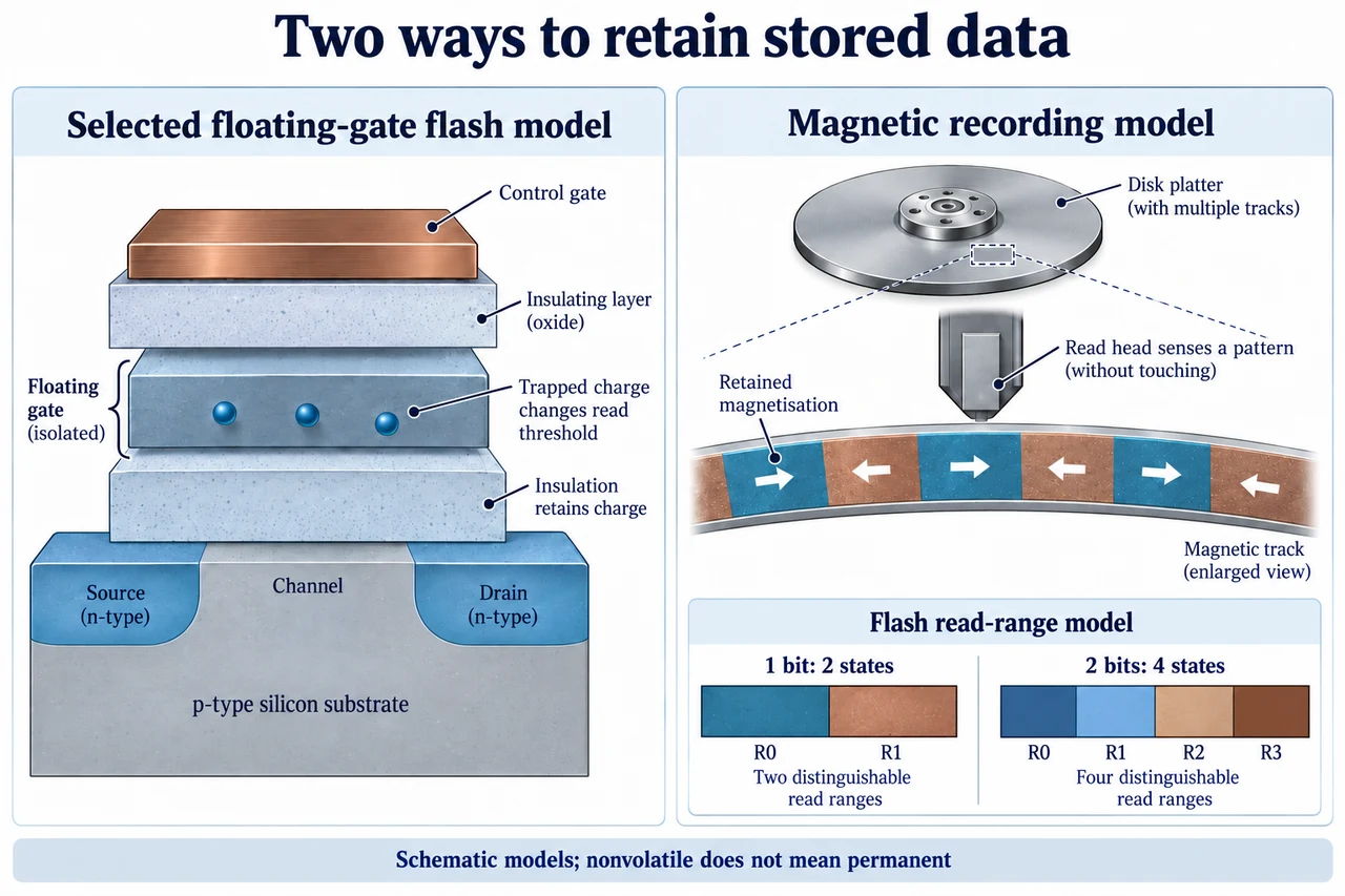
The left-hand illustration selects a simplified planar floating-gate transistor. An isolated charge-storage region sits within insulating layers between the control gate and the channel. Stored charge changes the threshold associated with reading the transistor; the reader distinguishes ranges rather than counting a literal dot for each file bit. The depicted dots and layer dimensions are conceptual. Modern flash can use a charge-trap structure rather than this particular floating-gate geometry, so the selected cross-section must not be mistaken for every NAND cell. Insulation permits retention without a continuously powered external charging circuit, but leakage, wear, interference and operating history make “nonvolatile” a bounded engineering property, not a promise of eternity.
The right-hand illustration magnifies a magnetic recording track. Retained magnetisation supplies a persistent pattern; a read head senses it while the powered drive positions the head and moves the medium. The enlarged arrows represent a recording model, not a counted population of grains or a claim that a logical bit is always exactly one grain. Coding and detection connect the physical signal to recovered data. Stability and the ability to change a recording state are competing design concerns. Seagate’s description of heat-assisted magnetic recording explains a selected approach in which local heating helps a write head change a stable recording region. It does not imply that ordinary data retention requires continuous heating or establish universal reliability, densities or the absence of all thermal effects.
Packing more bits into one flash cell requires distinguishing more read states. With b bits there are 2 raised to b possible bit patterns: 1 bit requires 2 states, 2 bits 4, 3 bits 8 and 4 bits 16. Micron describes these cases as SLC, MLC, TLC and QLC respectively. The plate shows only the two-state and four-state comparison to make the idea readable; its colours are not a universal assignment of zeros, ones or actual voltages. More distinctions within a limited measurement range demand control of overlapping distributions and errors. This reasoning alone does not rank finished products: controllers, coding, architecture, workload and product qualification can differ.
Use a fictional normalised read range of length 1 with equal, non-overlapping windows and levels exactly at their centres. Eight states then have window width 1/8 = 0.125 and centre-to-nearest-boundary margin 1/16 = 0.0625. Sixteen states have width 1/16 = 0.0625 and margin 1/32 = 0.03125. In this toy model the second margin is half the first. Real read distributions are neither perfectly sharp nor necessarily equally spaced, and no operating voltage or exact error rate follows. If noise or drift crosses a boundary, an incorrect raw decision is possible; appropriate error-correcting coding can recover some errors within its capacity. The model explains why distinguishability matters rather than certifying that every four-bit cell fails sooner than every three-bit cell.
Flash management also changes the meaning of a write budget. Data is organised into pages within larger erase blocks, so changing and reclaiming data can entail internal movement rather than one physical write for each host byte. A controller can manage valid-data relocation, bad blocks, error correction and wear distribution. These functions are related but not interchangeable: error correction does not itself ensure even wear, and garbage collection does not mean deleting the user’s chosen files. Define write amplification here as physical bytes written to flash divided by bytes written by the host during the same interval. A stipulated 100 GiB host-write interval with amplification 1.5 produces 150 GiB of physical writes. Against a stipulated 120 GiB of participating physical capacity, that is 150/120 = 1.25 capacity-equivalent full writes, not 1.5. This ideal average is not the erase-cycle count of every cell or an endurance warranty.
The system boundary matters as much as the medium. Data still buffered in volatile memory when power fails is not the same as data already persistently recorded. A filesystem’s apparent success, controller behaviour and durability guarantees need their own evidence. Likewise, nonvolatile storage is not a backup: deletion, corruption, device failure or loss can affect the only copy. Resource comparisons should include workload, energy, embodied materials, repairability and actual required reliability rather than one density label. Responsible disposal also needs an appropriate verified data-removal process; this lesson gives no secure-erasure procedure or promise that an ordinary file deletion removes every physical trace.
Image: illustration, not a documentary photograph.
Worked example: An invented flash system receives 100 GiB of host writes in an interval. Write amplification, defined as physical flash bytes written divided by host bytes written, is 1.5. Participating physical capacity is 120 GiB. Find physical writes and the average capacity-equivalent full writes. Separately compare eight and sixteen equally spaced state windows over a normalised range of length 1.
Physical writes = 100 × 1.5 = 150 GiB. Average capacity-equivalent full writes = 150/120 = 1.25; the denominator is stipulated physical capacity, not host writes.
Eight equal windows have width 1/8 = 0.125 and centre-to-boundary margin 0.0625. Sixteen have width 0.0625 and margin 0.03125.
The margin halves under this deliberately ideal model. No real voltages, uneven wear, erase counts, workload-dependent controller changes or error-rate measurements are specified.
Answer: 150 GiB physical writes and 1.25 average capacity-equivalent full writes. Toy read margins are 0.0625 for eight states and 0.03125 for sixteen.
Check your understanding: Keep host writes at 100 GiB and capacity at 120 GiB, but reduce write amplification to 1.2. What changes? How many distinguishable states are required to store three bits per cell? Explain why a retained physical state neither guarantees a retrievable file nor replaces a backup, and why the toy state model cannot rank real drive lifetimes.
Answer: Physical writes become 120 GiB, or 1 capacity-equivalent full write, a 20% reduction from 150 GiB. Three bits require 2³ = 8 distinguishable states. Retention concerns the medium’s recorded state; controller failure, damaged metadata or an unavailable interface can prevent retrieval. A backup addresses loss of the only copy and other failure paths, rather than merely providing nonvolatile media. The toy windows omit actual distributions, coding, wear, temperatures, controller policy and qualification, so they do not predict real retention or lifetime. Uniform capacity-equivalent writes are not identical per-cell erase counts.
Why: Keep information patterns, physical read states and device-level reliability separate. State every denominator and idealisation. A medium can retain data without guaranteeing crash durability, accessibility, privacy or a permanent archive.