Water distribution: height, pressure and finite storage
By How things work · myAudience
myAudience original generated educational illustration · Original commissioned illustration
Water distribution: height, pressure and finite storage
A public water network must move water from a source to places that need it, often at different elevations and with demand changing during the day. Pumping into an elevated tank can separate the timing of supply from the timing of demand. USGS describes this familiar tower arrangement. The tower does not manufacture water, and gravity does not make the whole service free of energy input: a pump or other upstream source supplied the stored gravitational potential energy. Some networks instead depend on direct pumping, natural elevation, reservoirs or combinations of these arrangements.
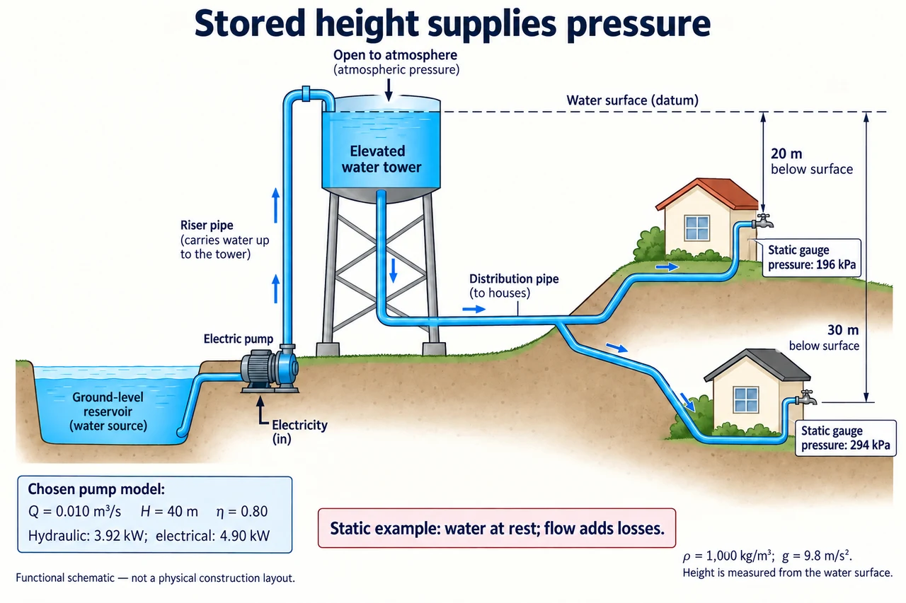
The plate separates the upward pump riser from the downstream distribution path. The dashed water-surface datum defines two vertical differences: one tap is 30 m below that surface and the other is 20 m below it. The height is not the tower’s roof height or the length of the pipe. In the declared static case, with water open to atmospheric pressure at the surface and the same atmosphere at the taps, the gauge pressures are 294 and 196 kPa. The diagram does not promise those pressures while water flows; its pump numbers are a separate chosen energy example. The blue arrows indicate route directions, not simultaneous motion during the static calculation; both example taps are closed.
Derive the static relation rather than treating it as a memorised tower rule. A water column of area A and height h has volume Ah, mass ρAh and weight ρAhg. Divide its weight by area to get the pressure difference Δp = ρgh. With chosen density 1,000 kg/m³ and g = 9.8 m/s², 30 m gives 294,000 Pa = 294 kPa. Atmospheric pressure is not counted twice: this is gauge pressure relative to the surrounding atmosphere. At rest, pipe shape does not create an extra pressure supply; elevation differences set the hydrostatic difference under these assumptions.
Flow changes the balance. A real pipe system transfers energy to friction and fittings and may need additional velocity head, so the usable pressure depends on demand, pipe conditions and elevation rather than h alone. In a hypothetical comparison, a 30 m available elevation head with a stated 8 m loss at the chosen flow leaves 22 m before any other specified terms; that corresponds to 215.6 kPa in the simplified accounting. The 8 m loss is given, not calculated from an unprovided diameter or universal rule. A blocked pipe and an open tap have different conditions even if the same tank stands nearby.
For the pump inset, choose water throughput Q = 0.010 m³/s and total required head H = 40 m, including whatever elevation and loss terms the model declares. Hydraulic power is ρgQH = 3,920 W. If pump-system efficiency is 0.80, electrical input is 3,920 / 0.80 = 4,900 W, or 4.90 kW. The difference is 0.98 kW transferred to other outputs under that steady model. A 40 m total pumping head must not be silently substituted for the taps’ 30 m and 20 m static heights. The chosen efficiency is illustrative, not a product rating or a motor-sizing instruction.
Storage also needs a water-volume balance. If a fictional usable tank contains 600 m³ above its minimum service level and there is no refill, outflow of 50 m³/h exhausts that usable inventory in 12 hours if the rate stays constant. With inflow 30 m³/h and outflow 50 m³/h, depletion is 20 m³/h and the same usable inventory lasts 30 hours. A falling level can reduce pressure before all water is gone, and real demand is variable, so neither division guarantees service to every tap. Branch continuity says that entering flow equals branch outflows plus accumulation and leaks, not that each branch gets an equal share.
An equitable network is evaluated at users’ points of service, including high elevations and distant locations, rather than only at the pump outlet. Leakage, maintenance interruptions and energy bills can fall unevenly across a community. Increasing pressure is not a universal cure: it can change leakage and equipment stresses, and water quality requires separate protection and testing. Compare supply reliability, affordability, resource conservation and transparent reporting. Water-quality, backflow and pressure-system work require the applicable standards and qualified practice; this lesson develops accounting and explanation, not a network operating procedure.
Image: illustration, not a documentary photograph. The water tower is an open-surface functional model with chosen static pressures and a separate pump-energy calculation; it is not a scale network or measured service guarantee.
Worked example: A tap is 25 m below an open water surface. Use ρ = 1,000 kg/m³ and g = 9.8 m/s² to find static gauge pressure. At a stated operating flow, a given 6 m head loss reduces the available head. A separate pump supplies 0.015 m³/s through total head 35 m at efficiency 0.75; find hydraulic and electrical power.
Static pressure = 1,000 × 9.8 × 25 = 245,000 Pa = 245 kPa.
Simplified remaining head = 25 − 6 = 19 m, corresponding to 186.2 kPa before other terms.
Hydraulic power = 1,000 × 9.8 × 0.015 × 35 = 5,145 W. Electrical input = 5,145 / 0.75 = 6,860 W = 6.86 kW.
Answer: Static pressure is 245 kPa; the given-loss model leaves 186.2 kPa. The separate pump transfers 5.145 kW hydraulically and requires 6.86 kW input in its chosen model.
Check your understanding: A usable tank inventory is 480 m³. Inflow is 25 m³/h and measured total outflow is 55 m³/h, including a 5 m³/h leak. Find the constant-rate depletion time; then remove only that leak. Why does a taller tower not by itself prove safe or continuous supply?
Answer: Initial depletion is 55 − 25 = 30 m³/h, giving 480 / 30 = 16 hours. With only the leak removed, outflow is 50 m³/h and depletion 25 m³/h, giving 19.2 hours. These are usable-volume, constant-rate estimates. Height can increase static pressure, but finite inventory, refilling, flow losses, changing demand and water quality remain separate constraints.
Why: State the system boundary, trace the mechanism, use consistent units and justify what the simplified calculation cannot establish.