Reinforced concrete: why the steel position matters
By How things work · myAudience
myAudience original generated educational illustration · Original commissioned illustration
Reinforced concrete: why the steel position matters
Concrete and steel cooperate rather than becoming one imaginary material with no weaknesses. Concrete can carry compression much more effectively than tension; steel reinforcement can carry tensile forces where appropriate bond and detailing transfer load between materials. FHWA’s archived 2016 bridge report explains these established mechanisms and why corrosion protection matters. Its historical specifications are not treated as current design rules. This lesson asks how a simply supported beam resists one chosen downward loading case, then tests which conclusions survive a changed geometry or support arrangement.
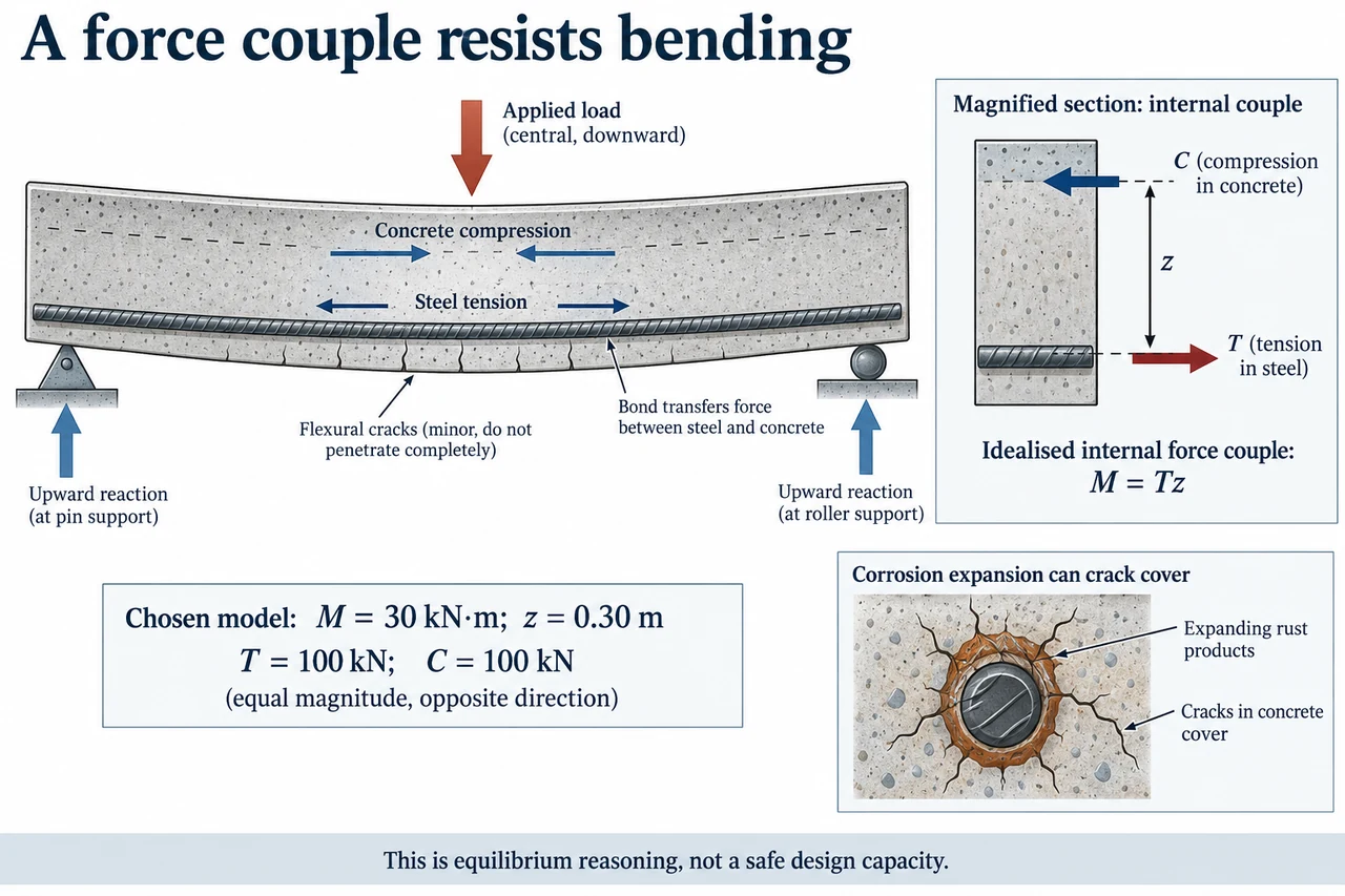
In the plate’s sagging beam, the upper region shortens in compression and the lower region extends in tension. The main longitudinal steel lies inside the lower concrete, above a visible cover layer, rather than underneath as a separate cable. Short bottom cracks represent tensile cracking in this bounded schematic; they are not drawn as a complete break. Bond at the steel–concrete interface transfers force, so simply placing a smooth loose object beside concrete would not establish the pictured cooperation. Reactions at the two end supports balance the downward load in the displayed simply supported case.
The separate section sketch isolates an idealised internal force couple. Equal and opposite horizontal forces C and T act along two lines separated by lever arm z. Their net horizontal force is zero, but they produce a moment of magnitude M = Tz. For the chosen M = 30 kN·m and z = 0.30 m, T = 100 kN and C = 100 kN. This is equilibrium accounting, not a capacity formula that certifies an unknown beam. The internal forces must arise from a feasible stress distribution, material properties, geometry, bond and detailing; none is established merely by dividing M by z.
Connect that section reasoning to external equilibrium with an original ideal beam model. For a 4 m simply supported span with a central 20 kN point load and self-weight deliberately omitted, symmetry gives 10 kN reaction at each end. Taking moments at the midspan section gives 10 × 2 = 20 kN·m. If a chosen section model has z = 0.25 m, its balancing force-couple magnitude is 20 / 0.25 = 80 kN. The external loading determines the required moment in this toy model; z affects the internal force needed to balance it. Neither calculation selects a safe steel area or validates construction.
Changing the support arrangement can change the bending pattern. A continuous member over a support can have a region whose tension face is at the top, so copying bottom bars from the displayed sagging example everywhere would be wrong. Shear effects also differ from the longitudinal bending couple; the plate does not provide a stirrup design or complete failure-mode analysis. Deflection, crack width, anchorage, fire, fatigue and durability introduce further constraints. An apparently small crack can have several causes, while some tensile cracking is anticipated in reinforced-concrete behaviour; a picture alone is insufficient to diagnose safety.
Consider a transfer question before making the common claim that more steel always fixes a beam. Under the ideal couple calculation, keeping M = 30 kN·m while reducing z from 0.30 to 0.20 m raises T from 100 to 150 kN. Adding nominal steel area does not automatically restore the old lever arm, bond, anchorage, concrete compression response or ductility. Force divided by area can describe a chosen average tensile stress, but real design needs applicable checks and material behaviour. We deliberately supply no allowable stress, strength reduction factor or rule for approving a structure.
The corrosion inset explains a second timescale. Corrosion products around reinforcement can expand and damage concrete cover, while lost steel section and weakened bond can impair the intended load path. FHWA describes chloride-associated damage in bridges; the diagram does not imply chlorides are the only possible cause. Ethical infrastructure decisions compare inspection, repair, durability, material production emissions and disruption over a service life. Deferring maintenance may transfer risk and cost to future users; replacing everything prematurely can also consume resources. Transparent evidence and qualified assessment matter more than a dramatic illustration or an unverified claim of sustainability.
Image: illustration, not a documentary photograph. The beam, section couple and corrosion inset are separate bounded concept models, not an actual bridge, a scale stress plot or a safe design capacity.
Worked example: An ideal simply supported 6 m beam carries one central 24 kN point load; neglect its own weight. Find the two reactions and the midspan moment. For a chosen internal lever arm of 0.36 m, find the equal force-couple magnitudes. Does this establish the capacity of a real beam?
Symmetry and vertical balance give 12 kN upward at each support.
At midspan, moment magnitude = 12 × 3 = 36 kN·m.
T = M/z = 36 / 0.36 = 100 kN; C = T. Material strength, bond, detailing and other limit states are not supplied.
Answer: Reactions are 12 kN each; required midspan moment is 36 kN·m; the chosen couple requires 100 kN per force. This does not establish safe real capacity.
Check your understanding: For M = 45 kN·m compare z = 0.30 and 0.25 m. A colleague says the same bottom-bar picture proves reinforcement belongs at the bottom over every support. Explain both the numerical and conceptual errors, and why the corrosion inset is not just cosmetic damage.
Answer: The required couple forces are 45 / 0.30 = 150 kN and 45 / 0.25 = 180 kN; a shorter lever arm raises the force demand. The tension region depends on loading and support conditions, and continuous-support regions may require top reinforcement rather than copying a sagging-span diagram. Corrosion can damage cover, steel section and bond, affecting load transfer as well as appearance; actual safety needs qualified assessment.
Why: State the system boundary, trace the mechanism, use consistent units and justify what the simplified calculation cannot establish.