Wings: separate lift, force balance and rotational control
By How things work · myAudience
myAudience original generated educational illustration · Original commissioned illustration
Wings: separate lift, force balance and rotational control
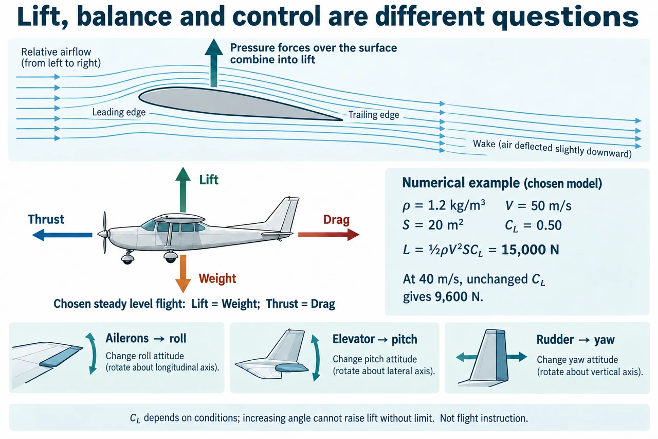
A wing changes the surrounding airflow and experiences a resultant aerodynamic force. NASA presents pressure forces over the surface and momentum changes in the air as compatible accounts of the same interaction. Lift is the component perpendicular to the relative flight direction; drag acts along that direction against relative motion. This definition does not mean lift is always vertically upward in the world. The plate deliberately uses a level, unbanked example so that its lift and weight arrows can be vertical, then separates that balance from the smaller control-surface panels.
Read the upper image as a qualitative flow schematic, not a measured computational-fluid-dynamics result. Air moves from left to right past the leading edge and leaves with a small downward wake component; the force on the wing is upward in this chosen view. Neither coloured particles nor arrival times have been paired across the two sides. The familiar equal-transit story is false: air separated near the front is not required to meet again at the trailing edge. A longer upper path alone cannot calculate lift, and symmetric wings can produce lift at suitable incidence. Pressure and momentum should not be presented as competing explanations that exclude each other.
The lift equation L = ½ρV²SC_L organises a model rather than supplying every missing fact. Here ρ is air density in kg/m³, V is relative airspeed in m/s, S is the declared reference area in m² and C_L is a dimensionless coefficient. Multiplying the units gives kg·m/s², which is a newton. C_L encodes geometry and flow conditions and normally requires experimental or appropriately validated modelling evidence. It depends on angle of attack and other conditions; assigning a constant value is an explicit comparison assumption, not a claim that all speeds or attitudes preserve it.
For the plate’s chosen ρ = 1.2 kg/m³, V = 50 m/s, S = 20 m² and C_L = 0.50, lift is ½ × 1.2 × 50² × 20 × 0.50 = 15,000 N. At 40 m/s with everything else held constant, the factor is (40/ 50)² = 0.64, so lift falls to 9,600 N. Retaining 15,000 N at that speed would mathematically require C_L = 15,000 / (½ × 1.2 × 40² × 20) = 0.78125. That calculation does not establish that a real wing can safely attain the coefficient. Flow separation and stall prevent unlimited lift growth by increasing angle of attack; this is a conceptual transfer, not a flight manoeuvre instruction.
The lower aircraft panel concerns translational balance. In its chosen steady level case, lift equals weight and thrust equals drag, so the net force vanishes and velocity is constant. Equal force pairs do not mean the individual forces disappear. If weight were 15,000 N while lift fell to 9,600 N and all other forces remained horizontal, the instantaneous vertical resultant would be 5,400 N downward. A real aircraft may change attitude, thrust direction or trajectory, so that instantaneous model is not a complete prediction of its later motion. Use the vector sum of forces; the largest named force alone does not determine acceleration in a general case.
Control surfaces chiefly generate moments that change attitude. Ailerons influence roll about the longitudinal, nose-to-tail axis; the elevator influences pitch about a lateral axis; the rudder influences yaw about a vertical body axis. The three small image panels name these axes, rather than promising that one surface directly commands a position or ground path. Pitching the nose upward is not identical to climbing, and yaw is not automatically a coordinated turn. Flight dynamics couples rotations, airflow, lift and energy; the simplified mapping is a starting point for reasoning about moments, not an operating checklist or universal response for every aircraft design.
Engineering judgement includes what the coefficient and balance conceal. Reducing density from 1.2 to 0.9 kg/m³ in the plate’s fixed-speed comparison reduces lift to 11,250 N, but a designer must also examine drag, structural load, stability, stall margins and measured performance. Social choices include noise, emissions, equitable access, land use and who bears consequences of failures. Public explanations should distinguish a proven mechanism from unsupported claims about a novel airfoil’s efficiency. A neat streamline picture or a favourable C_L value is not evidence that an aircraft is safe, economical or environmentally preferable over its lifecycle.
Image: illustration, not a documentary photograph. The airflow is qualitative, the four-force diagram is a chosen steady level case and the numerical card assumes an unchanged C_L. The rotational panels identify axes; they do not specify safe control inputs. These three levels of explanation are deliberately separate.
Worked example: For a chosen wing model use ρ = 1.0 kg/m³, V = 60 m/s, S = 15 m² and C_L = 0.60. Calculate lift, then compare a 48 m/s case at unchanged coefficient. Find the coefficient that would mathematically restore the first lift at 48 m/s and explain what remains unknown.
Initial lift = ½ × 1.0 × 60² × 15 × 0.60 = 16,200 N.
The speed ratio is 48/ 60 = 0.80; squared it is 0.64. Lift at unchanged C_L is 16,200 × 0.64 = 10,368 N.
Required C_L = 16,200 / (½ × 1.0 × 48² × 15) = 0.9375. Whether the wing actually attains this without separation or other limits needs measured evidence.
Answer: The chosen forces are 16,200 N and 10,368 N. The algebraic recovery coefficient is 0.9375; it is not a demonstrated operating capability.
Check your understanding: A learner says upper and lower air particles must reunite, and that the elevator makes an aircraft climb. Correct both claims. If the plate’s density falls to 0.9 kg/m³ at unchanged speed, area and coefficient, what lift follows and what does the result fail to establish?
Answer: Equal transit is not a flow requirement. The elevator produces a pitch moment; a climb depends on the resulting forces, velocity and energy, not nose angle alone. The chosen density ratio is 0.9/ 1.2 = 0.75, so lift is 15,000 × 0.75 = 11,250 N. This comparison does not determine later flight motion, stall limits or safety.
Why: Resolve the chosen force or energy boundary, state assumptions and distinguish a mathematical model from measured performance and safe operation.