Railways: why low resistance still needs adhesion
By How things work · myAudience
myAudience original generated educational illustration · Original commissioned illustration
Railways: why low resistance still needs adhesion
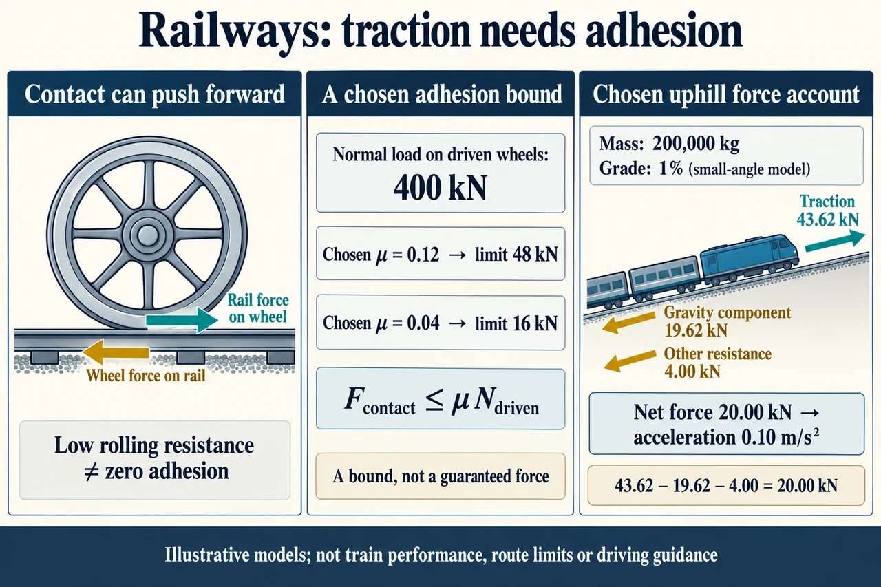
A railway vehicle must transfer force through its wheels to speed up, slow down and climb. Low rolling resistance is useful because a rolling vehicle need not dissipate as much energy as one sliding over a surface, but it does not mean that the wheel and rail should have no adhesion. A powered wheel needs a tangential contact force. The image's left panel separates the rail's forward force on the driven wheel from the wheel's backward force on the rail. These are a Newton's-third-law pair on different bodies; they do not cancel in the train's own force account. This lesson explains longitudinal traction, not signalling, safe separation, braking instructions or certified route performance.
A motor supplies a turning effect to a driven wheel. At the contact, the wheel tends to push the rail backward, and the rail pushes the wheel forward. Friction does not universally point opposite the vehicle's travel: its direction depends on the tendency for relative slipping at that contact and the forces and torques applied. In an ideal rigid-wheel rolling model, the instantaneous material point touching a stationary rail has zero velocity relative to the rail. Static contact does not itself provide the vehicle's energy: the motor receives electrical energy or energy from an engine and transfers it through the drivetrain. Real wheel-rail contact includes deformation and small relative motions; a perfect no-slip wheel is a useful reference, not a complete description of a railway contact patch.
The middle panel is a deliberately chosen adhesion bound, F_contact ≤ μ N_driven, for positive forward traction. Here N_driven is the normal load carried by the driven wheels, not automatically the weight of the whole train. With N_driven = 400 kN, chosen coefficients 0.12 and 0.04 give upper bounds of 48 kN and 16 kN. These coefficients are illustrative, not measured rail conditions or a universal steel-on-steel table. The inequality means that a requested force below the bound might be supported; it does not say that every contact force always equals μN. Motor power, wheel torque and control limitations can impose lower limits. A real traction-versus-slip curve is more complex than this simple cap.
The right panel chooses an uphill longitudinal account for a 200,000 kg train. Grade is rise divided by horizontal run, so 1% means tan θ = 0.01, not an angle of 1 degree. At this small angle take sin θ ≈ 0.01 and g = 9.81 m/s². The component of gravity down the track is then about 19.62 kN; the vertical weight is much larger and is not the arrow labelled 'Gravity component'. Add a chosen 4.00 kN of other resistance. To obtain acceleration 0.10 m/s², the net uphill force must be ma = 20.00 kN, requiring traction 43.62 kN. The net is the sum of the displayed forces, not another force to add. The drawn slope is exaggerated for visibility and cannot be measured to infer a grade.
Compare that request with the chosen caps. The 48 kN bound exceeds 43.62 kN, so adhesion alone would not rule out the requested acceleration in this limited model. This is not proof that a real train can provide the required torque or power. The 16 kN cap is below even the 23.62 kN needed to balance gravity and the chosen resistance. If the train is already moving uphill under that capped contact force and these fixed assumptions, acceleration is (16,000 − 23,620)/200,000 = −0.0381 m/s²: the uphill speed decreases. Adding unlimited motor power would not remove a contact-force cap. The model ignores changing resistance, load transfer, rotational inertia, contact dynamics and control responses, so this calculation is not a prediction of a real departure or a stopping distance.
At a chosen uphill speed of 10 m/s, the longitudinal traction account Fv is 436.2 kW. Its three terms are 196.2 kW associated with gaining gravitational potential energy, 40.0 kW associated with the chosen resistance and 200.0 kW associated with increasing translational kinetic energy. The last term is ma v, consistent with d(½mv²)/dt. This is an equivalent vehicle-translation account: it must not be interpreted as a stationary rail delivering 436.2 kW of physical work at an ideal no-slip contact point. Motor energy, wheel rotation and the mechanics of the drivetrain complete the physical energy account; real losses and auxiliary loads raise supply requirements. Grade or mass changes alter the gravity and acceleration terms even if a displayed engine power rating stays unchanged.
RSSB's adhesion research page, checked on 4 October 2026, describes moisture, leaf films and other contaminants as causes of low adhesion and explains why predictable braking is a railway-system concern. It also distinguishes established mitigation work from trials of new monitoring. A sensor, prediction or extra traction power cannot be assumed to guarantee every contact condition. Adhesion is relevant to braking as well as propulsion, but their control and safety requirements need separate treatment. Regenerative braking is a linked mechanism already taught elsewhere: recovery requires a suitable electrical destination and does not replace all braking functions. Signalling, interlocking, train detection, safe headways, suspension, curves and wear remain substantial unclosed parts of this technology family.
A useful railway design must serve people as well as move mass. Ask whose journey is possible with the station access, service pattern and ticket price, and who bears construction, noise and maintenance burdens. A lower vehicle energy demand does not by itself establish the whole system's lifecycle emissions: electricity supply, occupancy and infrastructure also matter. An accessibility improvement may be valuable even when it adds equipment or energy use. The plate explains a contact-force pair, a chosen cap and a longitudinal balance; it does not draw an actual train's wheel arrangement or prove a route's capacity. Evidence-based comparisons should declare the service and accounting boundary instead of treating one fictional coefficient or power total as a universal railway rating.
Worked example: For a new chosen train, mass is 120,000 kg, grade is 0.5%, g = 9.81 m/s² and other uphill-motion resistance is 3 kN. Use the small-angle approximation. Find traction needed for acceleration 0.05 m/s² and its longitudinal power account at 12 m/s. If driven-wheel normal load is 250 kN, compare chosen adhesion coefficients 0.08 and 0.04. Calculate the capped acceleration in the second case, assuming the train is already moving uphill. Finally compare the original plate's approximate gravity component with the exact trigonometric value.
Gravity component ≈ 120,000 × 9.81 × 0.005 = 5,886 N. Required net acceleration force is 120,000 × 0.05 = 6,000 N. Traction request is 5,886 + 3,000 + 6,000 = 14,886 N = 14.886 kN.
The longitudinal power account is 14,886 × 12 = 178,632 W, or 178.632 kW. It splits into 70.632 kW for gravity, 36 kW for the chosen resistance and 72 kW for translational acceleration, ignoring wheel rotational inertia and drivetrain losses.
The chosen caps are 0.08 × 250,000 = 20,000 N and 0.04 × 250,000 = 10,000 N. The first does not rule out the request on adhesion grounds alone; the second cannot support the requested acceleration. With the second cap, a = (10,000 − 5,886 − 3,000)/120,000 ≈ 0.0092833 m/s², still positive but below the request.
For the original 1% grade, exact mg sin(arctan 0.01) ≈ 19,619.019 N rather than 19,620 N. The small-angle result exceeds it by about 0.981 N, roughly 0.005%. That small approximation error does not justify ignoring the much larger real-model uncertainties.
Answer: The new request is 14.886 kN and its chosen longitudinal power account is 178.632 kW. Chosen caps are 20 and 10 kN; the second gives about 0.00928 m/s² under the declared assumptions. The original grade approximation differs by about 0.981 N from the exact component.
Check your understanding: Do the two opposite contact arrows cancel in the train free-body diagram? Is μN always the actual traction? Can a larger engine guarantee more acceleration in the 16 kN capped original case? Does Fv mean that a stationary rail supplies the train's energy?
Answer: No: the reaction acts on the rail, outside the train free body. μN is a chosen upper bound, not a fixed delivered force. More engine power alone does not remove the contact cap, which is already below the chosen uphill resistance. Fv is the translation-equivalent account here; in ideal no-slip rolling the instantaneous stationary contact point receives no work from the rail. Energy comes through the motor/drivetrain, and a full account includes rotation and losses.
Why: Identify the body or control-volume boundary and reference frame, derive the force and energy account with units, and justify which conclusions the chosen model cannot establish.