Ship propulsion: momentum, reference frames and wake energy
By How things work · myAudience
myAudience original generated educational illustration · Original commissioned illustration
Ship propulsion: momentum, reference frames and wake energy
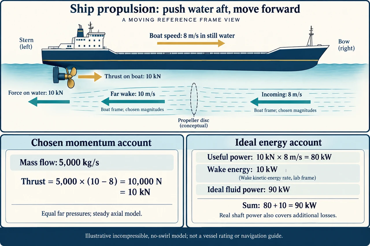
A propeller-driven ship moves forward because its propulsion system transfers momentum to water in the opposite direction. In the plate, the stern is on the left and the bow is on the right: thrust on the boat points right, while the force on the water points left. These equal and opposite forces act on different bodies. A propeller is not a screw engaging a rigid thread in the sea; blade pressure forces arise from motion through a fluid. A shaft supplies torque and energy, whether its source is an engine, an electric motor or a more complex propulsion arrangement. This lesson concentrates on a chosen axial momentum model, leaving buoyancy, stability, navigation and complete marine propulsion design as separate topics.
The upper flow arrows use the boat's frame. Suppose the boat travels at 8 m/s through water that was initially still relative to the shore. In the boat frame the incoming water moves aft with speed magnitude 8 m/s, and the chosen far wake moves aft with magnitude 10 m/s. Both arrows therefore point left; they are not conflicting statements that the sea travels forward and backward at once. In the shore frame, the far wake has been accelerated aft to 2 m/s while the boat moves forward. The abstract stream lies outside the hull: it does not imply that water enters the cabin or flows through a particular ship's internal pipe. Consistent reference frames are essential before calculating forces or energy.
For a steady control volume with equal pressure far upstream and far downstream, an ideal axial thrust magnitude is mass flow multiplied by the increase in aft velocity magnitude: T = ṁ(v_wake − v_in). The plate chooses ṁ = 5,000 kg/s, giving T = 5,000 × (10 − 8) = 10,000 N, or 10 kN. Units kg/s × m/s are newtons. This is momentum transferred per second; it is not a force from water mass alone. A pressure difference exists across an ideal actuator disk because the propulsor adds energy. Applying a no-work Bernoulli equation directly across that disk would discard the very energy addition being modelled. NASA's elementary propeller account supplies the momentum-theory reference; here the explicitly incompressible, no-swirl fluid model is used for water, not claimed to validate a marine device from an aircraft example.
The ideal fluid-power account is ½ṁ(v_wake² − v_in²) = ½ × 5,000 × (100 − 64) = 90,000 W. Useful power associated with overcoming the boat's resistance at this speed is TV = 10,000 × 8 = 80,000 W. In the shore frame the chosen outgoing water's added kinetic-energy rate is ½ṁ(10 − 8)² = 10,000 W. Thus 80 kW plus 10 kW is 90 kW: useful vehicle power plus kinetic energy left in the wake. The wake value is a rate, not 10 kJ stored once. All three numbers belong to one ideal account; an actual shaft must also cover additional hydrodynamic losses, and the upstream engine or electrical supply has its own losses. None is a whole-vessel fuel efficiency or an actual shaft rating.
The split follows algebraically if the incoming water was initially still and V is the boat speed. Set Δv = v_wake − V. Then T = ṁΔv and ideal fluid power is ½ṁ[(V + Δv)² − V²] = TV + ½ṁΔv². At fixed thrust, wake kinetic-energy rate becomes T²/(2ṁ). In the chosen model, transferring momentum to a larger mass flow with a smaller velocity increase wastes less energy in the far wake. Doubling ṁ to 10,000 kg/s at unchanged 10 kN thrust gives Δv = 1 m/s, wake power 5 kW and ideal fluid power 85 kW. The useful fraction changes from 80/90 ≈ 88.9% to 80/85 ≈ 94.1%. These are propulsive-model fractions, not guarantees that simply enlarging a propeller improves every boat: draft, blade loading, hull interaction and other constraints matter.
The ideal account also exposes a common mistake about stationary thrust. At V = 0, useful translational power TV is zero, but the propulsor can still transfer momentum and leave kinetic energy in moving water. A zero useful-motion term does not mean a spinning propeller requires no energy. In a real ship, the hull alters the inflow and the wake contains swirl, turbulence and nonuniform velocities. Shaft bearings, the drivetrain and the power source introduce further terms. Manufacturer explanations distinguish propeller arrangements such as fixed and controllable pitch; this article does not select a pitch, blade geometry or operating speed. The force and energy relationships are established physics, while a particular efficiency improvement still requires device-specific evidence.
Cavitation is another limit that a smooth axial diagram omits. When local pressure falls below the liquid's vapour pressure, vapour cavities can form; they are not simply air deliberately pumped into the water. Their collapse can contribute to noise and erosion, depending on where and how it occurs. This is distinct from ventilation, where gas from outside enters the flow. The Wärtsilä definition is used for this mechanism, without adopting promotional claims about a particular propeller design. IMO identifies propeller cavitation, engines and hull vibration as sources of underwater noise. Its public material includes work on noise reduction and trade-offs with energy efficiency; some page announcements still describe 2025 events as upcoming, so they are not treated as a verified current implementation timetable.
A ship's transport service connects ports and communities, but evaluating it requires more than the ideal wake fraction. Consider fuel production, exhaust or electrical supply, repair access, cargo or passenger service, worker exposure and underwater effects on marine life. A change that reduces one energy term can shift cost or noise elsewhere; affected coastal communities should not be invisible in the accounting. The illustration explains opposed forces, boat-frame flow magnitudes and a chosen ideal energy balance, not a propeller construction drawing or a navigation guide. Full buoyancy and stability, hull resistance, cavitation prediction, machinery safety and specific decarbonisation pathways remain open parts of this family. A responsible comparison states which outcomes were measured and which are only modelled.
Worked example: Use a different ideal steady axial account: boat speed through initially still water is 6 m/s, mass flow 4,000 kg/s and chosen thrust 8,000 N, with equal far pressures and no swirl. Find aft velocity increase, boat-frame far-wake magnitude, useful power, wake kinetic-energy rate, ideal fluid power and useful fraction. Then double mass flow at fixed thrust and boat speed. Explain why neither fraction rates an actual engine or establishes the best propeller.
Δv = T/ṁ = 8,000/4,000 = 2 m/s. Far-wake aft magnitude in the boat frame is 6 + 2 = 8 m/s; in the shore frame outgoing water moves aft at 2 m/s.
Useful power is TV = 8,000 × 6 = 48 kW. Wake kinetic-energy rate is ½ × 4,000 × 2² = 8 kW. Ideal fluid power is ½ × 4,000 × (8² − 6²) = 56 kW, also 48 + 8. The useful fraction is 48/56 = 6/7 ≈ 85.7%.
At 8,000 kg/s, Δv = 1 m/s and far-wake magnitude is 7 m/s. Useful power stays 48 kW; wake power is ½ × 8,000 × 1² = 4 kW; ideal fluid power is 52 kW. The useful fraction becomes 48/52 = 12/13 ≈ 92.3%.
These fractions use an ideal fluid boundary, not fuel-to-transport or whole-vessel efficiency. Real hull interaction, shaft losses, blade loading, draft, noise and other constraints are omitted; a model improvement does not certify a practical design.
Answer: The first case gives Δv = 2 m/s, 8 m/s boat-frame far wake, 48 kW useful, 8 kW wake and 56 kW ideal fluid power, about 85.7% useful fraction. Doubling flow gives 1 m/s increase, 7 m/s far wake, 4 kW wake and 52 kW fluid power, about 92.3% useful fraction; real design evidence remains necessary.
Check your understanding: Why do both water arrows point aft although the boat travels forward? Can zero boat speed mean zero propeller power? Is cavitation just outside air entering the water, and does a chosen 88.9% useful fraction establish a vessel's fuel efficiency?
Answer: The water arrows describe magnitudes in the boat frame; the initially still water appears to approach aft and the propeller increases its aft velocity. At zero boat speed TV is zero but momentum transfer and wake energy can remain nonzero. Cavitation involves vapour cavities forming at sufficiently low local liquid pressure; gas drawn in from outside is ventilation. The 88.9% fraction belongs only to the chosen ideal fluid account, excluding real propulsion and supply losses and therefore not rating an actual vessel.
Why: Identify the body or control-volume boundary and reference frame, derive the force and energy account with units, and justify which conclusions the chosen model cannot establish.