Exhaust recovery: terminal temperatures, exchanger evidence and useful service
By How things work · myAudience
myAudience original rendered teaching illustration. Image: illustration, not a documentary photograph. · Operator-authored generated illustration; scientific model reviewed separately.
Exhaust recovery: terminal temperatures, exchanger evidence and useful service
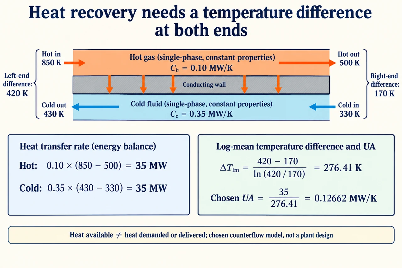
Recoverable exhaust energy is an opportunity rather than an automatic useful output. Start with the preceding lesson's chosen nonideal cycle: 70 MW enters as equivalent external heat, 15 MW leaves as net shaft work and 55 MW remains in the hot return stream's cooling from 850 K to 300 K. The plate examines one separate counterflow receiver that removes some of that heat across a solid wall. Hot fluid moves left to right; cold fluid moves right to left. Downward arrows represent energy transfer through the wall, not stream mixing. The receiver is not a steam turbine or a combustor recuperator. Choose steady, single-phase, constant-capacity-rate fluids, negligible environmental loss and pressure drop, and uniform effective U for this model.
The hot stream's capacity rate Ch = 0.10 MW/K follows from 100 kg/s multiplied by the stipulated cp = 1 kJ/(kg K). Choose its outlet at 500 K, so Q = Ch(850 − 500) = 35 MW. The separate cold stream is specified only through Cc = 0.35 MW/K and inlet 330 K; its outlet must then be 430 K because Q/Cc = 100 K. For example, chosen mass flow 175 kg/s and chosen cp = 2 kJ/(kg K) have that capacity rate; this is not a claim about a real water state or actual fluid properties. The remaining hot cooling from 500 K to 300 K transfers 20 MW elsewhere. The whole surrogate still closes: 70 = 15 + 35 + 20 MW. Recovered heat is counted once, not added as a new energy input.
Counterflow terminal differences pair temperatures at the same physical end. On the left, hot inlet 850 K faces cold outlet 430 K, giving ΔTleft = 420 K. On the right, hot outlet 500 K faces cold inlet 330 K, giving ΔTright = 170 K. The plate's terminal brackets identify these pairs. Subtracting the two inlet temperatures, 850 − 330 = 520 K, mixes opposite ends and is not the local driving difference. Subtracting outlet temperatures likewise does not generally provide a useful terminal pair. The DOE fundamentals handbook's counterflow diagrams distinguish these physical pairings. Its June 1992 technical edition is historical teaching support; a recent hosting path does not make its contents a newly validated design standard.
For ideal counterflow under the stated assumptions, Q = UA ΔTlm, with ΔTlm = (ΔTleft − ΔTright)/ln(ΔTleft/ΔTright). The numbers give 250/ln(420/170) = 276.409… K and UA = 35/276.409… ≈ 0.126624 MW/K. UA combines an effective transfer coefficient and area; this exercise does not determine either separately. Using the incorrect inlet difference 520 K would produce 0.0673077 MW/K, underestimating the required conductance for these stipulated terminal conditions. Using the arithmetic mean 295 K also differs from the logarithmic mean. Multipass geometry needs an appropriate correction or a different model; phase change, losses and varying capacity rates require revisiting this simple relation rather than blindly reusing its displayed result.
A cold outlet hotter than the hot outlet is not automatically impossible in counterflow because those outlets are at opposite ends. Test a chosen cold outlet of 600 K while retaining hot 850 → 500 K and Q = 35 MW. Energy balance requires Cc = 35/(600 − 330) ≈ 0.129630 MW/K. The terminal differences become 250 K and 170 K, both positive; ΔTlm ≈ 207.435 K and required UA ≈ 0.168727 MW/K. Thus the original UA cannot support all the new stipulated endpoints. If Cc stayed 0.35 MW/K, heating to 600 K would instead require 94.5 MW, contradicting the retained 35 MW. A target cold outlet of 900 K would make the left driving difference negative and cannot be obtained by this stated passive exchanger. Temperature ordering, capacity rates and transfer conductance must agree together.
Fouling introduces thermal resistance and can alter pressure drop, while thermal expansion and corrosion affect materials and maintenance. Reduced UA does not preserve the same heat rate and all four temperatures unless another quantity changes. For a chosen 20% conductance reduction, UA becomes approximately 0.101299 MW/K. Holding the original terminal differences hypothetically fixed would allow only 28 MW; the endpoints would actually have to be solved again with the stream balances. A system consequence may also appear upstream if exhaust back pressure or internal pumping demand changes. Compare inspection evidence on consistent conditions, rather than interpret every reduced outlet temperature as a universal improvement. The plate supplies a conductance requirement for a bounded teaching case, not exchanger sizing permission or maintenance instructions.
Now declare a separate fictional service model before calculating benefits. Over a 24-hour window the cycle runs for 90% of the time, or 21.6 hours, at the chosen 70 MW equivalent heat input. For this accounting exercise alone, treat the 15 MW net shaft output as 15 MW electricity before any new recovery-system demand, with an ideal conversion assumption. Heat delivery consumes an additional 2 MW whenever the cycle is on, leaving 13 MW export. A customer needs only 20 MW of suitable heat for six hours, and assume operation is independently distributed over those demand hours: coincidence is 5.4 hours. Export becomes 280.8 MWh and useful heat 108 MWh, against 1512 MWh equivalent heat input. Their sum divided by input is 25.714…%, a chosen service-energy ratio, not a measured fuel-based CHP efficiency.
Without heat delivery in that stipulated service comparison, export was 324 MWh. Recovery loses 43.2 MWh of electricity but adds 108 MWh of wanted heat, a net arithmetic increase of 64.8 MWh across two different service forms. Electricity and heat are not equally interchangeable, so the energy sum alone cannot decide whether this is better. EPA's CHP explanation separates net useful outputs, fuel input and the value of different energy forms; its typical performance figures are not adopted here. Ask whether suitable heating demand actually coincides with generation, which alternative supplies would be displaced, whose access improves and whose pollution or water burdens change. No fuel energy, emissions factor, price or environmental benefit is supplied by this fictional exercise. Explain those gaps before making a lifecycle claim. Image: illustration, not a documentary photograph.
Worked example: For the plate, calculate both stream heat transfers, terminal differences, logarithmic mean and required UA. Then test a 600 K cold outlet at the same 35 MW, and calculate the declared 24-hour useful-service comparison.
Hot transfer = 0.10 × (850 − 500) = 35 MW. Cold transfer = 0.35 × (430 − 330) = 35 MW. Terminal differences are 420 K and 170 K.
ΔTlm = 250/ln(420/170) = 276.409… K; UA = 35/276.409… = 0.126624… MW/K. Remaining hot cooling = 0.10 × (500 − 300) = 20 MW, closing 70 = 15 + 35 + 20.
For a 600 K cold outlet at 35 MW, Cc = 35/270 = 0.129630… MW/K. Terminal differences = 250 K and 170 K; ΔTlm = 80/ln(250/170) = 207.435… K; UA = 0.168727… MW/K.
Service operation = 24 × 0.9 = 21.6 h. Heat-input energy = 70 × 21.6 = 1512 MWh. Export = (15 − 2) × 21.6 = 280.8 MWh. Wanted heat = 20 × 6 × 0.9 = 108 MWh.
Combined chosen service ratio = (280.8 + 108)/1512 = 25.714…%. Baseline export = 15 × 21.6 = 324 MWh, so electricity changes by −43.2 MWh and the sum of useful service energies by +64.8 MWh.
Answer: The original exchanger transfers 35 MW with UA ≈ 0.126624 MW/K. The 600 K target requires a smaller cold capacity rate and greater UA ≈ 0.168727 MW/K. In the separate service model, 280.8 MWh electricity plus 108 MWh wanted heat gives a 25.714…% equivalent-heat-input service ratio; this is not fuel-based CHP efficiency or proof of lifecycle benefit.
Check your understanding: Why is a 600 K cold outlet not automatically forbidden by a 500 K hot outlet? Why is 35 MW multiplied by the full 24 hours not useful heat? If the same 21.6 on-hours are not independently spread across the six demand hours, bound the wanted heat and service ratio without inventing a schedule.
Answer: The two outlets lie at opposite ends. At 600 K the paired driving differences remain positive, but energy balance requires Cc ≈ 0.129630 MW/K and the required UA rises; those changes cannot be omitted. Recoverable thermal power is not necessarily suitable or wanted, and operation is only 21.6 h. On-time can avoid at most 18 non-demand hours, so overlap with six demand hours is between 3.6 h and 6 h. Wanted heat is therefore 72–120 MWh at 20 MW. Electricity remains 280.8 MWh under the stated fixed on-time/internal demand. The sum-to-input ratio is between 352.8/1512 = 23.333…% and 400.8/1512 = 26.5079…%. The assumed independent-overlap value lies inside these bounds, but no particular real schedule or fuel/emissions benefit is established.
Why: Use paired terminal temperatures, capacity and conductance together; distinguish potential recovery, demand coincidence, conditional expectations and deterministic bounds.