Protection exposure: squaring an average hides the clearing history
By How things work · myAudience
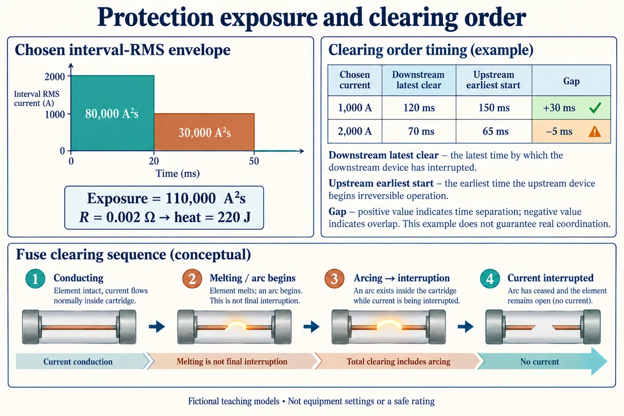
Image: illustration, not a documentary photograph. · Operator-authored generated illustration; scientific model reviewed separately.
Protection exposure: squaring an average hides the clearing history
Protection is a sequence of physical and informational actions, not an instantaneous label saying safe. Start with the earlier radial-system lesson: a sensor and decision element can request interruption, while a separate device must actually stop the path. Here we examine two deeper questions. How much electrical heating accumulates before current stops? Does the latest downstream clearing still precede the earliest upstream operation when times have uncertainty? Our boundary is one chosen resistive element and an independently stipulated serial-device timing account. It is not a complete substation model. Real fault sources, grounding, waveforms, devices and people exposed require evidence this arithmetic does not provide.
For a constant resistance R, instantaneous resistive power is i(t)²R. Integrating over a declared interval gives electrical energy converted into heat, E = R∫i(t)²dt. The integral alone has units A²s, often written I²t; multiplying by resistance in ohms produces joules. Thus a quoted current-squared exposure is not already an energy, and certainly not an arc-flash incident-energy result in joules per area. If resistance changes substantially with temperature, it belongs inside the integral. If heat leaves the element, its stored thermal-energy rise is not equal to the entire electrical input. A calculation can be dimensionally correct while representing too narrow a boundary to answer a safety question.
Choose two intervals whose stipulated mean-square currents can be represented by constant interval-RMS magnitudes: 2,000 A for 0.02 s, then 1,000 A for 0.03 s, followed by zero current. The rectangular drawing is this chosen envelope, not a trace of instantaneous alternating current. Its two exposure contributions are 2,000² × 0.02 = 80,000 A²s and 1,000² × 0.03 = 30,000 A²s. Their sum is 110,000 A²s. With a separately chosen constant resistance of 0.002 Ω, the heating input is 220 J. No manufacturer clearing curve, measurement, conductor withstand value or actual fuse melting threshold was used to obtain those numbers.
A tempting shortcut replaces the envelope with its time-weighted mean magnitude: (2,000 × 0.02 + 1,000 × 0.03)/0.05 = 1,400 A. Squaring that mean and multiplying by 0.05 s gives only 98,000 A²s, or 196 J for the chosen resistance. It misses 12,000 A²s and 24 J because squaring rewards variation: the mean of squares is greater than the square of the mean unless the magnitude is constant. An equivalent RMS for the whole 0.05 s window is √(110,000/0.05) = approximately 1,483.24 A. This mean-magnitude shortcut is not the signed mean of an actual AC waveform; the latter can be zero while heating remains substantial.
Time also has more than one meaning. A fusible element beginning to melt does not establish that all current has stopped; an arc can persist until final interruption. Schneider’s technical explanation distinguishes melting, arcing and total clearing. Its time-current bands distinguish minimum melting from maximum clearing, and its current-limiting discussion requires additional evidence beyond simple curve separation. We use the distinction, not its particular device examples, ratios, historical standards prescriptions or assumed tolerances. A breaker similarly needs a completed interruption, not merely a correct trip request. Actual voltage, available fault current and device interrupting capability remain separate engineering questions that an exposure integral cannot settle.
Now consider a different, explicitly hypothetical timing table. At a chosen current of 1,000 A, downstream total clearing can take 0.08–0.12 s, while the upstream element’s earliest irreversible operation begins at 0.15 s. The conservative separation is 0.15 − 0.12 = 0.03 s. At another chosen current of 2,000 A, downstream clearing spans 0.04–0.07 s, but upstream operation might begin at 0.065 s. The conservative gap is −0.005 s: the ranges overlap. Looking only at average times would conceal that possibility. These rows assume the serial devices experience the stipulated common current before interruption; they are not settings, a tested pairing, or a full-range coordination certificate.
Duration matters even when the first peak stays unchanged. Extend the second 1,000 A interval from 0.03 s to 0.06 s, rather than adding another 0.06 s to it. Total duration becomes 0.08 s and exposure becomes 80,000 + 60,000 = 140,000 A²s; the chosen heat input rises to 280 J. The additional 60 J follows from the extra 0.03 s, not a larger first current. Real materials, temperature-dependent resistance, cooling, source transients and current-limiting behaviour could change the result. Maintenance evidence must therefore connect measured condition, decision chain and actual interrupting performance. A neat exposure total does not justify handling equipment or assuming that an apparently disconnected path is safe.
Read the plate as three separate teaching devices: the rectangular interval-RMS envelope, a two-row uncertain-timing account, and a conceptual distinction between melting and final clearing. They are related questions, not one calibrated prediction of a real fuse. A lower exposure can be useful while a required interruption order still fails, and a backup action can protect equipment while disconnecting more people. An evidenced choice needs actual device data, the full relevant fault range, assembly and conductor constraints, maintenance records and consideration of essential services. The appropriate conclusion from our negative timing gap is to reject the claimed guaranteed order in this chosen model, not to improvise a replacement setting. Image: illustration, not a documentary photograph.
Worked example: For the stipulated 2,000 A interval-RMS envelope for 0.02 s and 1,000 A envelope for 0.03 s, R = 0.002 Ω constant, derive exposure, heating, mean-magnitude shortcut error and equivalent whole-window RMS. Then evaluate both timing rows and the second-interval extension to 0.06 s. Does any calculation establish safe equipment settings?
The squared-current terms are 80,000 and 30,000 A²s, hence exposure 110,000 A²s. Multiplying by 0.002 Ω gives 220 J electrical heating input. No stored temperature rise follows without heat capacity and heat-loss information.
The time-weighted envelope magnitude is (40 + 30)/0.05 = 1,400 A. Its square multiplied by 0.05 s gives 98,000 A²s, hence 196 J. The shortcut understates exposure by 12,000 A²s and heat by 24 J. The actual signed AC mean is a different quantity and is not this calculation.
Whole-window equivalent RMS = √(110,000/0.05) = √2,200,000 ≈ 1,483.24 A. Squaring that value and multiplying by the duration recovers the stipulated exposure; no empirical waveform was measured.
At the first timing condition use earliest upstream start minus latest downstream clearing: 0.15 − 0.12 = +0.03 s. At the second use 0.065 − 0.07 = −0.005 s. The second ranges overlap; the first positive margin certifies only that chosen one-case ordering, not the whole relevant range.
Extending the second interval to a total of 0.06 s gives duration 0.08 s and exposure 80,000 + 60,000 = 140,000 A²s. Heat becomes 280 J, an increase of 60 J. It does not add a further 0.06 s on top of the original 0.03 s.
Reject any claim of a safe setting, fuse rating, interrupting capability or arc incident energy from these surrogates. Actual devices, source conditions, current-limiting behaviour, material/cooling evidence and full-range tested coordination remain absent.
Answer: 110,000 A²s and 220 J; the squared-mean shortcut gives 98,000 A²s and 196 J, missing 24 J. Equivalent RMS is approximately 1,483.24 A. Timing gaps are +30 ms and −5 ms. The extended second interval gives 140,000 A²s/280 J over 80 ms. Only the declared arithmetic and model ordering are established.
Check your understanding: In a separate chosen envelope, 1,500 A lasts 0.02 s and 500 A lasts 0.06 s. Use the same constant resistance. Find exposure/heat and the squared time-weighted mean result. A separate changed timing case gives latest downstream clearing 0.09 s and earliest upstream operation 0.08 s. Can its lower exposure guarantee the required order or prove a safe installation?
Answer: Exposure = 1,500² × 0.02 + 500² × 0.06 = 45,000 + 15,000 = 60,000 A²s, hence 120 J. Mean envelope magnitude = (30 + 30)/0.08 = 750 A; the shortcut gives 750² × 0.08 = 45,000 A²s, hence 90 J, understating by 15,000 A²s/30 J. Timing gap = 0.08 − 0.09 = −0.01 s, so a 10 ms overlap remains. The exposure total is lower than the main case but says nothing by itself about guaranteed order, material limits or interrupting adequacy. Do not exchange a smaller number for omitted evidence.
Why: Distinguish dimensions, interval mean-square representation, conservative timing boundaries and the evidence needed for real protection.